Angular pneumatic gripper
a pneumatic gripper and angular technology, applied in the direction of gripping heads, manipulators, load-engaging elements, etc., can solve the problems of assembly faults, precision in the control of the movement of the gripper jaws, and the embodiment, etc., to achieve the effect of increasing the force of the transmission arm
- Summary
- Abstract
- Description
- Claims
- Application Information
AI Technical Summary
Benefits of technology
Problems solved by technology
Method used
Image
Examples
Embodiment Construction
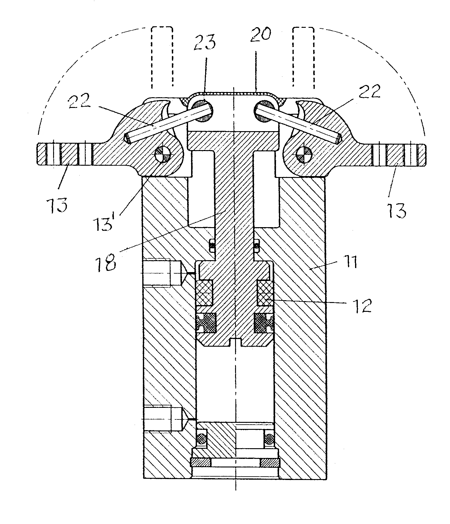
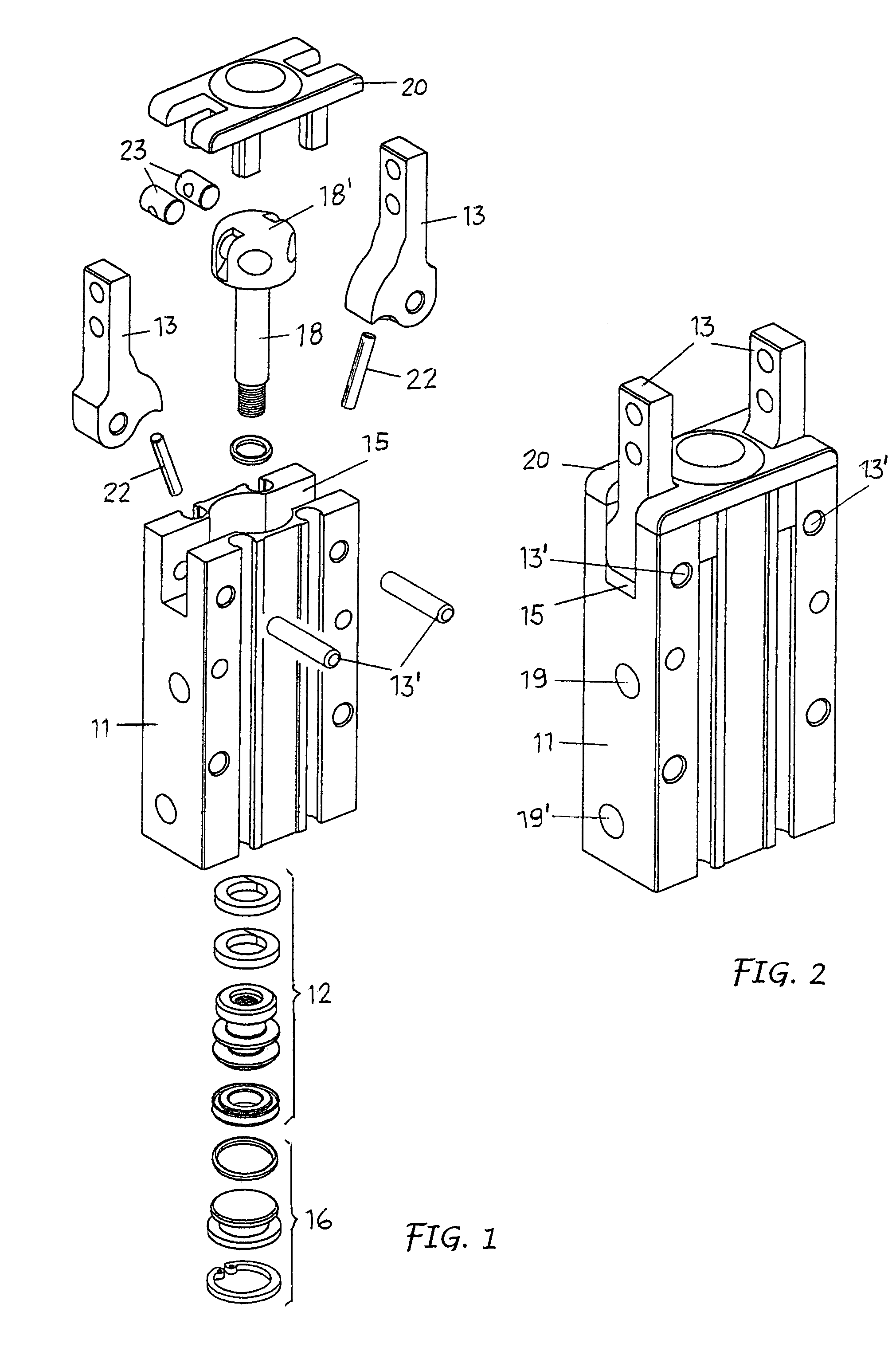
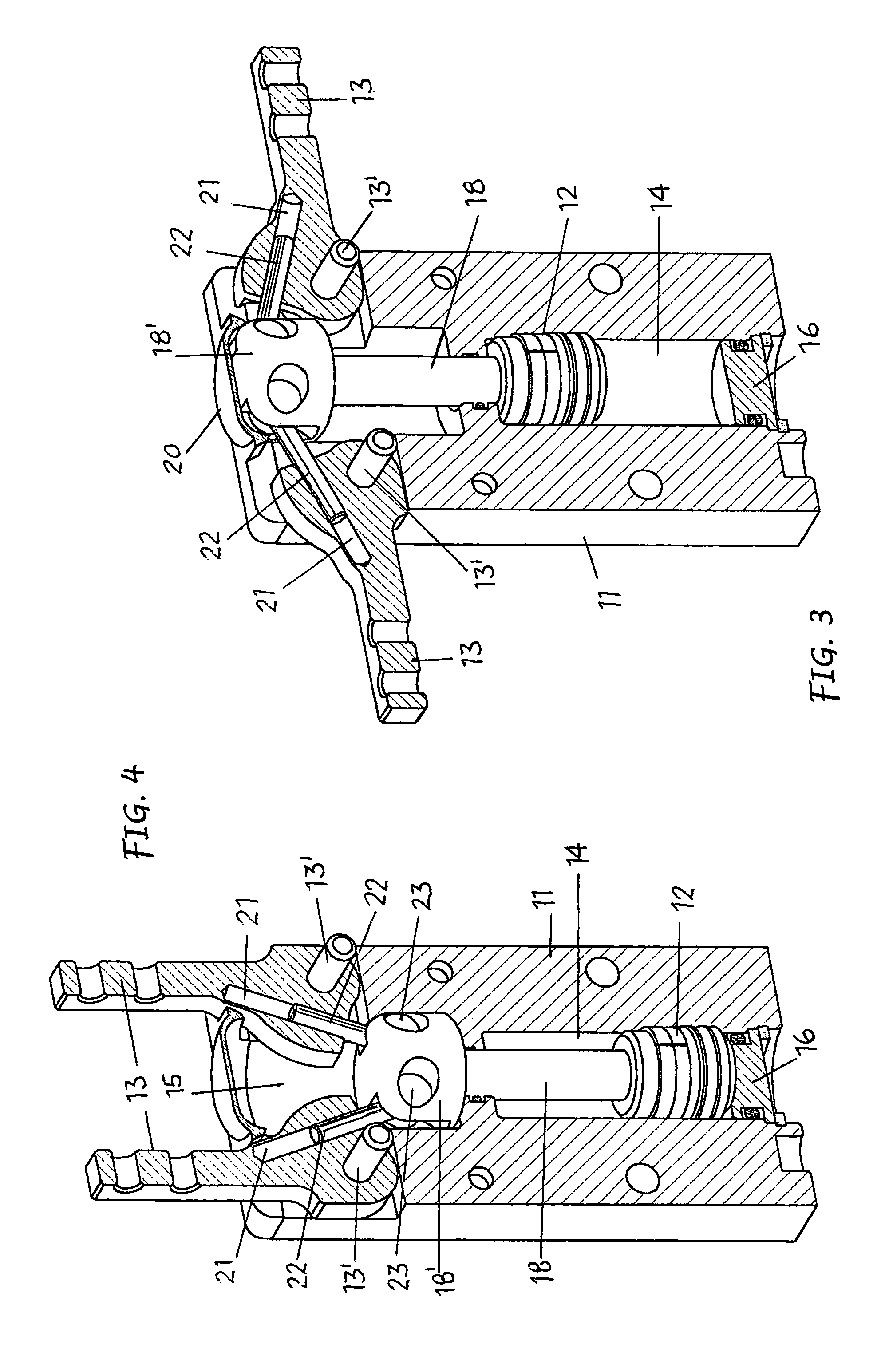
[0019]As represented, the gripper includes a gripper body 11, a control piston 12 and a couple of gripper jaws 13.
[0020]The gripper body 11 in one part forms a cylinder chamber 14 and the other part, a recess 15. At one of its ends, the chamber 14 is closed by a cover 16, whereas the opposite end opens towards the recess 15 through an intermediate hole 17.
[0021]The control piston 12 is housed and slides in the chamber 14 and is equipped with a stem 18 which passes through a seal into the intermediate hole 17 and terminates with a head 18′ on a level with the recess 15. The piston can be single acting or, as shown in the drawings, double acting. In the second case and as shown in FIGS. 5 and 6, there are two entrance / exit ports 19, 19′ at the ends of the chamber 14 of a fluid under pressure from opposite sides of the piston for the alternative movements of the latter.
[0022]The gripper jaws 13 are assembled symmetrically in the recess 15 of the gripper body from opposite sides of the ...
PUM
 Abstract
Description
Claims
Application Information
 - R&D
- Intellectual Property
- Life Sciences
- Materials
- Tech Scout
- Unparalleled Data Quality
- Higher Quality Content
- 60% Fewer Hallucinations
Browse by: Latest US Patents, China's latest patents, Technical Efficacy Thesaurus, Application Domain, Technology Topic, Popular Technical Reports.
© 2025 PatSnap. All rights reserved.Legal|Privacy policy|Modern Slavery Act Transparency Statement|Sitemap|About US| Contact US: help@patsnap.com


