Apparatus and method for improved illumination area fill

a technology of illumination area and illumination apparatus, applied in the direction of lighting and heating apparatus, instruments, semiconductor devices for light sources, etc., can solve the problems of not being suitable for all led illumination needs, not optimal in collection efficiency, and chromatic aberration generated by design that is particularly undesirabl

Active Publication Date: 2007-02-06
SIGNIFY HLDG BV
View PDF88 Cites 151 Cited by
  • Summary
  • Abstract
  • Description
  • Claims
  • Application Information

AI Technical Summary

Problems solved by technology

This is a relatively efficient optical solution for a small device, but not optimum in collection efficiency.
A major drawback of this method is chromatic aberration generated by the design that is particularly undesirable when utilized in ‘white’ LED systems.
While very useful for flashlights and some other devices, this is not appropriate for all LED illumination needs.
Attempts to generate a smooth beam from either of these configurations, generally with the addition of a diffuser, result in a substantial loss of efficiency.

Method used


Image

  • Apparatus and method for improved illumination area fill
  • Apparatus and method for improved illumination area fill
  • Apparatus and method for improved illumination area fill

Examples


Embodiment Construction

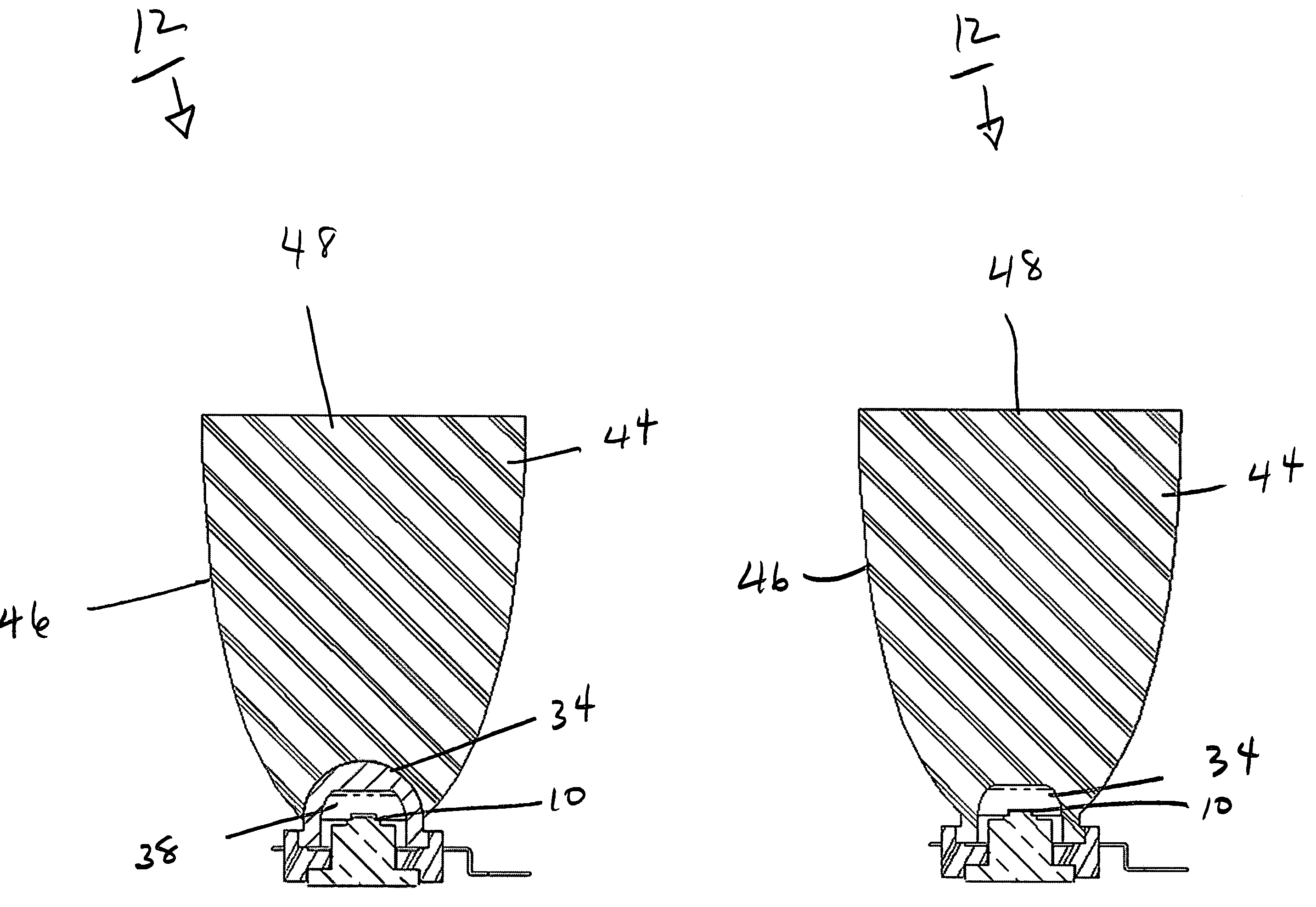
[0042]The preferred embodiment of the invention is directed to light emitting diodes (LED) and a method of collecting and distributing the energy radiated from them with increased energy efficiency. In fact, in the case of LED light sources, the preferred embodiment results in energy efficiencies approximately equal to or better than 90%. However, it is to be expressly understood that the invention is not limited to LED light sources, but may be employed with incandescent, plasma arc, fluorescent light sources or any type of light source now known or later devised, particularly those with similar or equal energy efficiencies. In addition, it must be understood that the term, “light” is used in its broadest sense as including the ultraviolet and infrared portions of the spectrum and that any light frequency which can be approximately modeled by optical ray tracing is contemplated was being within the scope of the invention.

[0043]Devices utilizing the invention would be used in genera...


PUM


Abstract

A reflector for a light source, such as an LED, is provided with a shape which efficiently collects and directs energy to an illumined surface whereby almost 100% of the light is collected and distributed into a designer composite beam. The shape in one embodiment is comprised of three zones beginning with a parabolic surface of revolution at the base of the reflector, followed by a transition or straight conic zone and ending with an elliptical zone. In another embodiment the reflector shape is determined according to a transfer function which allows for arbitrary designer control of the reflected rays at each point on the reflector, which when combined with direct radiation from the source, results in a designer controlled composite beam or illumination. The device is more than 90% energy efficient and allows replacement of higher power, less energy efficient light sources with no loss in illumination intensity.

Description

RELATED APPLICATIONS[0001]The present application is related to U.S. Provisional Patent Application Ser. No. 60 / 558,199, filed on Mar. 30, 2004, which is incorporated herein by reference and to which priority is claimed pursuant to 35 USC 119.BACKGROUND OF THE INVENTION[0002]1. Field of the Invention[0003]The invention relates to the field of methods and apparatus for providing illumination and in particular to methods and apparatus that are energy efficient, typically in excess of 90% energy efficiency and thus are specially suitable for low power light sources, thereby allowing replacement of higher power, less energy efficient light sources with no loss in illumination intensity.[0004]2. Description of the Prior Art[0005]The typical LED emitter radiates its light energy in a nearly hemispherical beam pattern. Most LED applications require substantial modification of this output beam profile to provide useful energy. The typical means of modifying this LED energy in the body of pr...

Claims


Application Information

Patent Timeline
Patent Type & Authority Patents(United States)
IPC IPC(8): F21V7/00G02B27/10B60Q1/04F21K99/00F21L4/00F21V7/04F21V7/09F21V13/04G02B17/06H01L33/58H01L33/60
CPCF21V7/0091F21V7/04F21V7/09F21K9/137G02B19/0028G02B19/0061F21V13/04H01L33/58H01L33/60F21Y2101/02F21K9/233F21Y2115/10
Inventor HOLDER, RONALD G.RHOADS, GREG
Owner SIGNIFY HLDG BV
Why Eureka
Try Eureka