Eureka AIR delivers breakthrough ideas for toughest innovation challenges, trusted by R&D personnel around the world.

Packaging and dispensing device with disengaging mechanism

Inactive Publication Date: 2007-02-06
LOREAL SA
View PDF8 Cites 0 Cited by
  • Summary
  • Abstract
  • Description
  • Claims
  • Application Information

AI Technical Summary

Benefits of technology

[0011]It is another object of the invention to provide a device for packaging and dispensing a product and which has a small number of parts which are easy to assemble.
[0022]Furthermore, the sleeve arrangement can limit the movement of the well inside the sleeve. Thus, by way of example, the stem can preferably have a length defined between the lug and the well bottom that is substantially equal to a height of the sleeve, with this corresponding height defined between the arrangement to limit travel of the cup and a dispensing aperture in the sleeve rendering the product accessible for topical application. Also, by way of example, this stem length is preferably substantially equal to a height of the grooved wall on the center-line of the spiral, i.e., the height inside the base along which the spiral or helical groove is formed.
[0029]Advantageously, the device preferably includes a cap capable of being retained on the base which enables the dispensing aperture on the sleeve to be closed off to render the product inaccessible. The cap preferably completely covers the sleeve and is held on the base, thus preventing rotation of the sleeve relative to the base when the cap is mounted on the device. This arrangement can prevent crushing of the product contained in the cup against the bottom of the cap.

Problems solved by technology

However, because the user does not know the exact number of turns to be applied to the second tubular element relative to the first tubular element, he or she might be induced to force the rotational action at the limit of travel in either the upper position or the lower position, with the risk of disengaging the means protruding radially from the cup from at least one of the grooves.

Method used


Image

  • Packaging and dispensing device with disengaging mechanism
  • Packaging and dispensing device with disengaging mechanism
  • Packaging and dispensing device with disengaging mechanism

Examples


Embodiment Construction

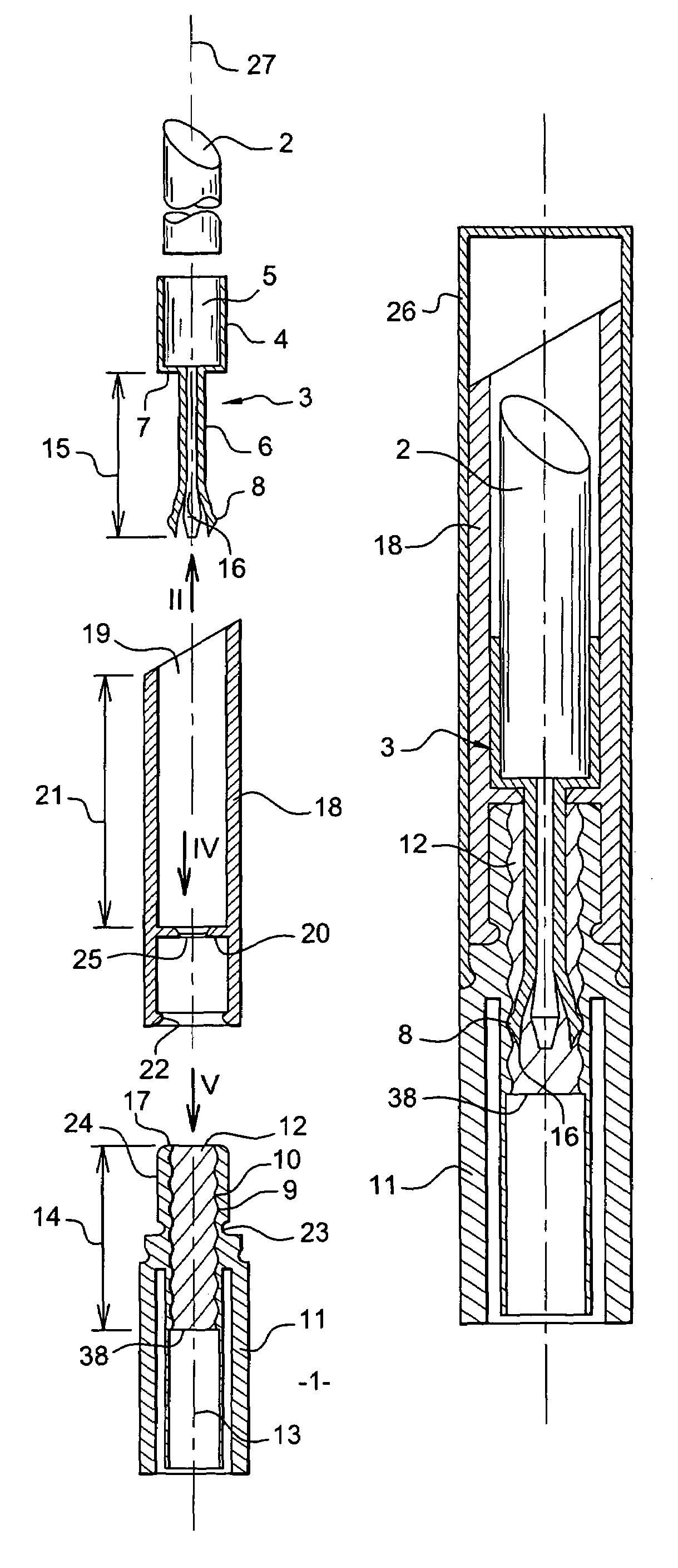
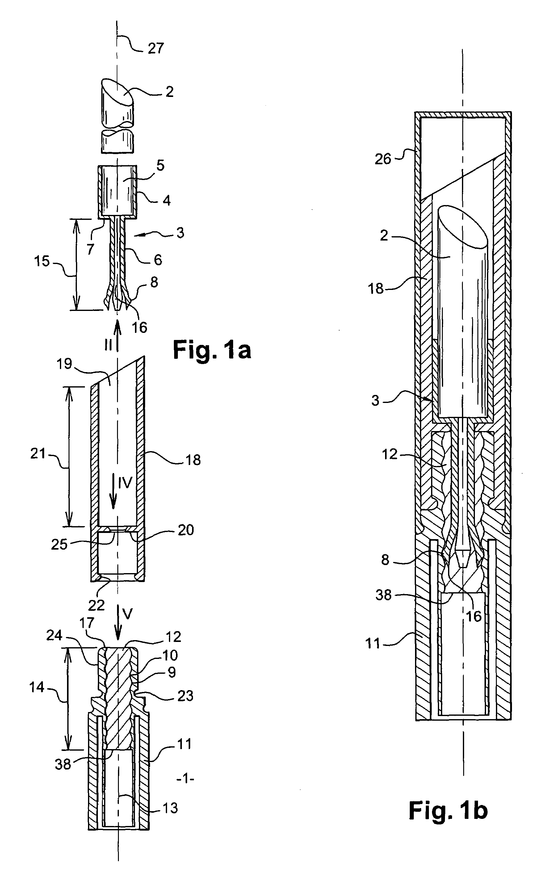
[0040]FIG. 1a shows a packaging and dispensing device 1 for a product 2. The product 2 is preferably a dispensable product, such as a cosmetic or body hygiene product. In this example, the product 2 takes the form of an oblong truncated tablet for application as lipstick.

[0041]The device 1 includes a cup 3 in which the product 2 is placed. In particular, the cup 3 includes a well 4 having a recess 5 designed to hold the product 2 in a stable manner. The recess has a cylindrical shape for example and preferably includes fluting on its inner circumference to facilitate retention of the product tablet 2.

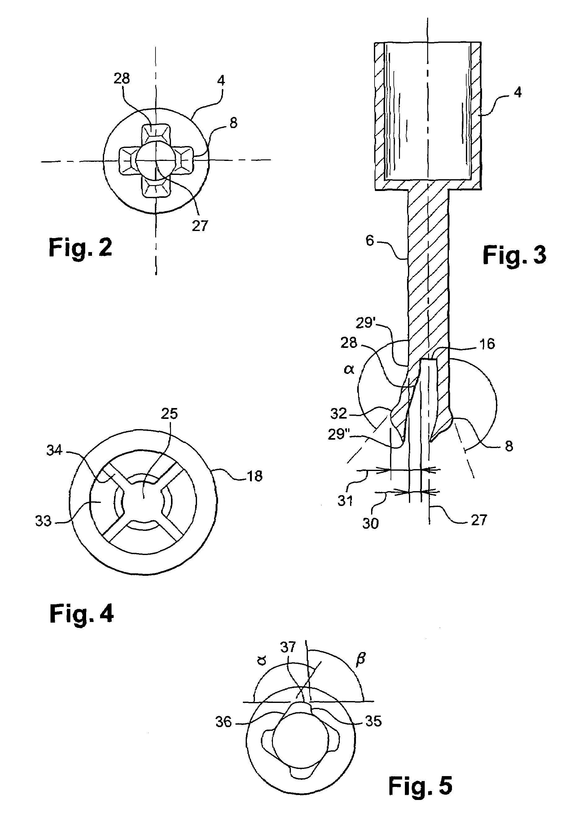
[0042]The cup 3 is also fitted with a stem 6 extending perpendicular to the bottom 7 of the well 4. The stem 6 includes at least one lug 8 intended to engage with a groove 9 provided on an inner wall 10 of a base 11 which is recessed to at least partially accommodate the stem 6. In effect, movement of the lug 8 in the groove 9 enables the stem 6 to penetrate more or less deeply into the...


PUM


Abstract

A packaging and dispensing device for a friable product, in particular a cosmetic product. The device includes a hollow base, and a cup intended to accommodate the product in a well. The cup includes at least one lug on a stem fixed below the well. The lug is flexible and engages with a helical groove in the inner wall of the base. The lug can be disengaged from the groove, in particular at the ends of the groove. The arrangement allows “free” rotation in a plane orthogonal to an axis of the spiral. The device includes a sleeve mounted in free rotation about the base, whereas it is fixed in rotation with the cup. The cup moves axially as a function of rotation of the sleeve relative to the base.

Description

CROSS-REFERENCE TO RELATED APPLICATIONS[0001]This document claims priority to French Application Number 03 04431, filed Apr. 9, 2003 and U.S. Provisional Application No. 60 / 470,500, filed May 15, 2003, the entire contents of which are hereby incorporated by reference.BACKGROUND OF THE INVENTION[0002]1. Field of the Invention[0003]The invention relates to a packaging and dispensing device, and particularly to a packaging / dispensing device that is suitable for the packaging of friable solid or semi-solid cosmetic products such as lipsticks or block deodorant formulations.[0004]2. Discussion of Background[0005]Packaging devices are known in the prior art, for example, in the arrangement disclosed in FR-A-2,755,592. This arrangement includes a cup containing a friable product, in which the cup incorporates means protruding radially from its outer lateral circumference that engage with a lengthwise groove provided in a first tubular element.[0006]U.S. Pat. No. 5,172,993 also describes a ...

Claims


Application Information

Patent Timeline
IPC IPC(8): A45D40/04A45D40/20B43K21/08B43K23/00
CPCA45D40/04A45D2040/0043
Inventor HABATJOU, JACQUES
Owner LOREAL SA
Why Eureka
Eureka Blog
Learn More