Quantum optical CNOT gate

a quantum optical and gate technology, applied in the field of nondeterministic quantum cnot gates, can solve the problem that two qubit gates are not easily implemented in optics

Inactive Publication Date: 2007-02-06
THE UNIV OF QUEENSLAND
View PDF0 Cites 44 Cited by
  • Summary
  • Abstract
  • Description
  • Claims
  • Application Information

AI Technical Summary

Benefits of technology

[0005]The invention is a non-deterministic quantum CNOT gate for photon qubits, comprising an interferometer to receive two target photon modes and two control photon modes and to cause a sign shift by splitting and remixing of the target photon modes, conditional on the presence of a photon in one particular control photon mode, so that the target photon qubit swaps modes if the control quantum qubit is in one mode but does not if the control photon qubit is in the other mode, provided a coincidence is measured between the control and target output photon modes.

Problems solved by technology

Two qubit gates are not easily implemented in optics.

Method used


Image

  • Quantum optical CNOT gate
  • Quantum optical CNOT gate
  • Quantum optical CNOT gate

Examples


Embodiment Construction

1. Non-Deterministic Quantum CNOT Gate

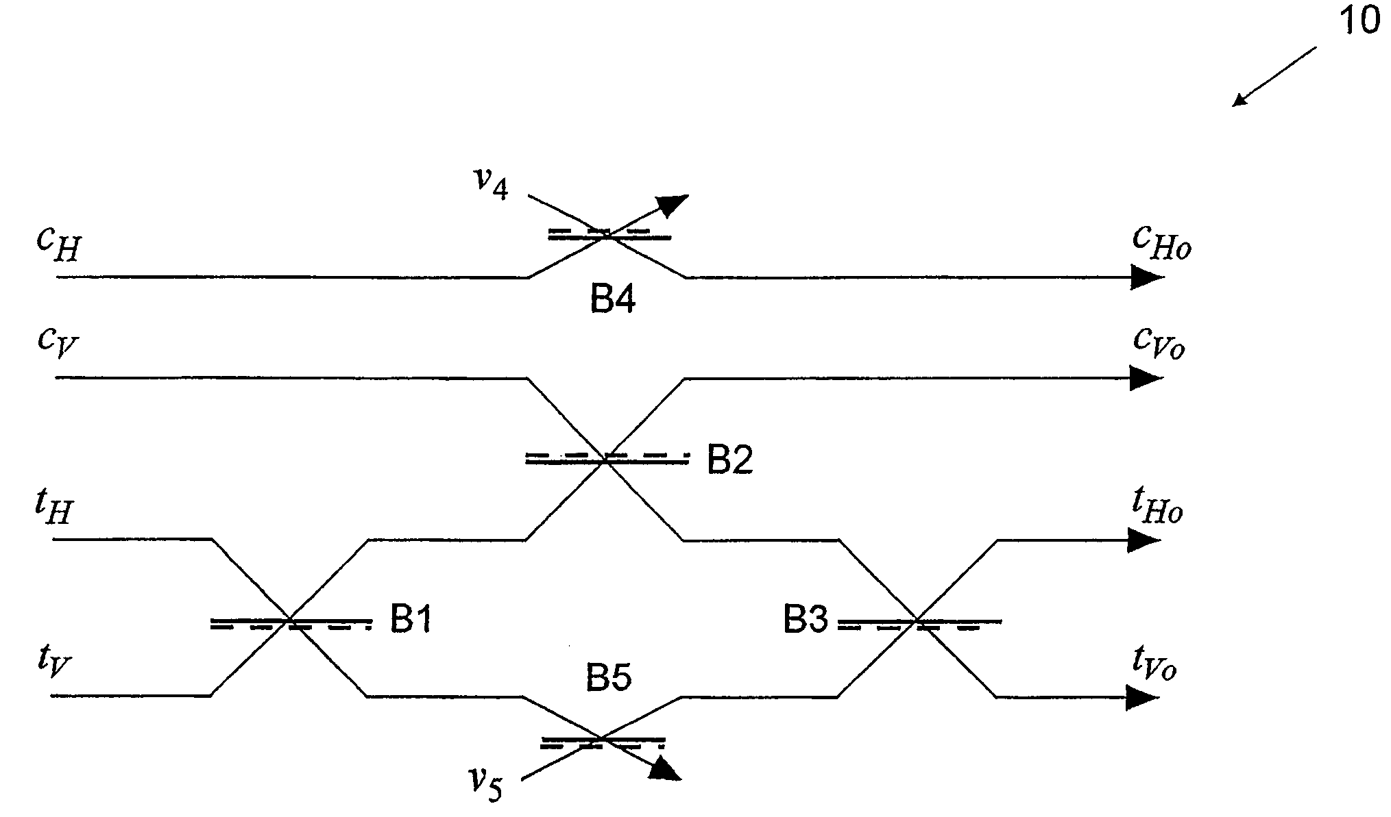
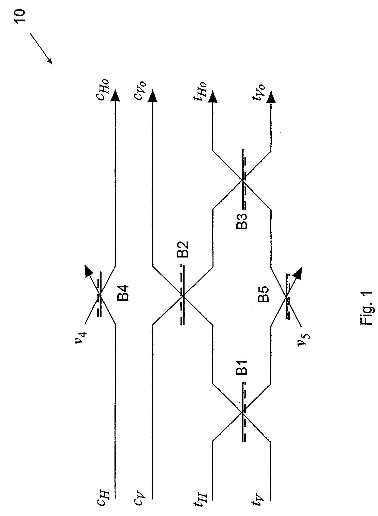
[0023]Referring first to FIG. 1, the non-deterministic quantum CNOT gate 10 comprises five beamsplitters, B1, B2, B3, B4, and B5 which are all assumed asymmetric in phase. That is, it is assumed that the operator input / output relations (the Heisenberg equations) between two input mode operators (ain and bin) and the corresponding output operators (aout and bout) for the beamsplitters have the general form:

[0024]aout=η⁢⁢ai⁢⁢n+1-η⁢⁢bi⁢⁢nbout=1-η⁢⁢ai⁢⁢n-η⁢⁢bi⁢⁢n(1)

where η (1−η) is the reflectivity (transmitivity) of the beamsplitter. Reflection off the bottom produces the sign change except for B2 and B4 which have a sign change by reflection off the top. This phase convention simplifies the algebra but other phase relationships will work equally well in practice. Beamsplitters B1 and B3 are both 50:50 (η=0.5). The beamsplitters B2, B4 and B5 have equal reflectivities of one third (η=0.33).

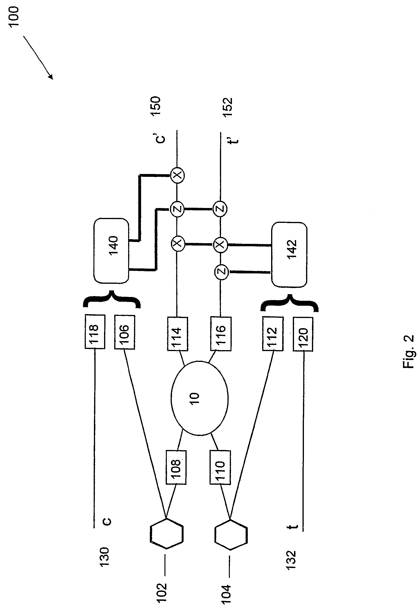
[0025]We employ dual rail logic such that the “control in” ...


PUM


Abstract

A nondeterministic quantum CNOT gate (10) for photon qubits, with success probability 1/9, uses beamsplitters (B1–B5) with selected reflectivities to mix control and target input modes. It may be combined with an atomic quantum memory to construct a deterministic CNOT gate, with applications in quantum computing and as a Bell-state analyser.

Description

TECHNICAL FIELD[0001]This invention concerns a non-deterministic quantum CNOT gate for photon qubits. It may be used in a deterministic CNOT gate. Such a deterministic CNOT gate would find many applications in Quantum Information Technology including as a Bell-state analyser and as a key element in an Optical Quantum Computer.BACKGROUND ART[0002]Classically, information can be encoded digitally by using a collection of systems which can each be placed in one of two distinct states, labelled as zeros and ones. Each system carries one “bit” of information. On the other hand quantum mechanics has systems that can be placed in states, called “superpositions”, that exist simultaneously as zeros and ones. For example information could be encoded with single photons by labelling a horizontally polarized photon, |H>, as a one and a vertically polarized photon, |V>, as a zero. But a photon can also be in a superposition of these two states such as 1 / √{square root over (2)}(|H>+|V>...

Claims


Application Information

Patent Timeline
Patent Type & Authority Patents(United States)
IPC IPC(8): H01L29/06G06N99/00
CPCB82Y10/00H04L9/0858G06N99/002G06N10/00
Inventor RALPH, TIMOTHY CAMERON
Owner THE UNIV OF QUEENSLAND
Why Eureka
Try Eureka