Filter monitoring system

a technology of filter monitoring and filter system, which is applied in the direction of separation processes, instruments, nuclear elements, etc., can solve the problems of fluid filter system clogging, refueling equipment may contaminate contaminate the high-quality fuel with contaminants, so as to increase resource efficiency and minimize expense

Active Publication Date: 2007-02-06
HAMILTON SUNDSTRAND CORP
View PDF8 Cites 63 Cited by
  • Summary
  • Abstract
  • Description
  • Claims
  • Application Information

AI Technical Summary

Benefits of technology

[0010]The present invention therefore provides a filter system which monitors the filter element to determine when the filter element is expected to reach a particular clogged level to more closely correlate filter replacement with a maintenance schedule to minimize expense and increase resource efficiency.

Problems solved by technology

While most aircraft fuels are subject to stringent quality standards, storage and refueling equipment may contaminate the high quality fuel with contaminants.
This contamination may still occur even though efficient filtration and water separating equipment is utilized whenever fuel is transferred from one point to another.
Fluid filter systems typically become contaminated and clogged over time.
This practice results in operation without filtration of the fluid, creating the possibility of component contamination.
Although filter elements are replaced on a routine basis, the replacement interval is typically conservatively specified, due to varying operating conditions which may result in unnecessary maintenance and an unneeded expense.
This may further increase the scheduled maintenance expense.
Disadvantageously, such conventional monitoring systems are mechanical and may fail due to vibration and pressure oscillations; the interval between trigger indication and eventual clogging or bypass varies with the level of new contaminant introduction; and extraordinary contamination events are undetected until the trigger level is reached.

Method used


Image

  • Filter monitoring system
  • Filter monitoring system
  • Filter monitoring system

Examples


Embodiment Construction

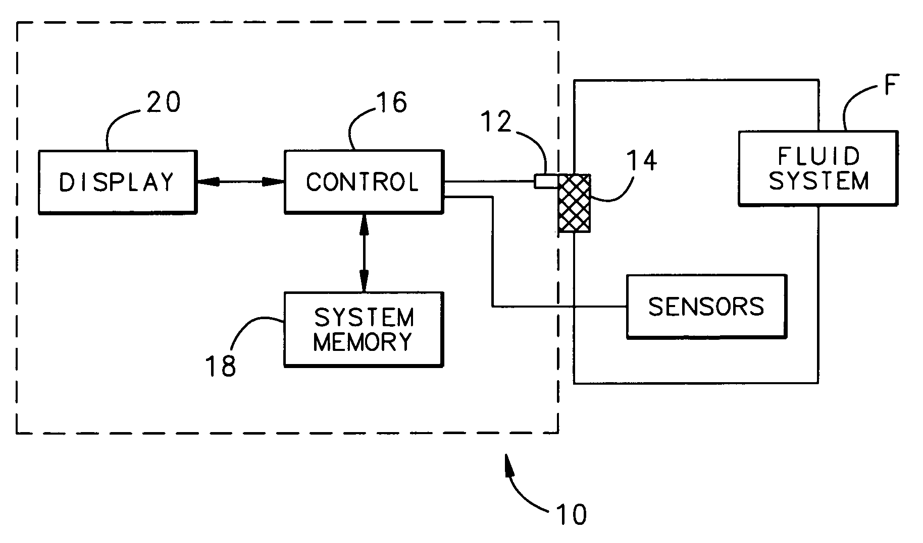
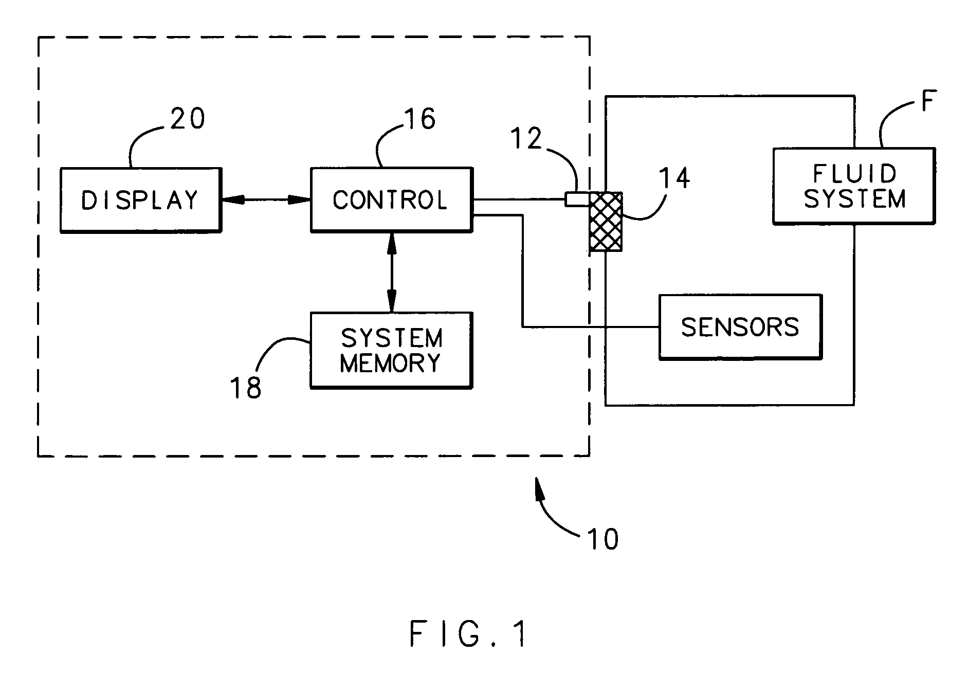
[0015]FIG. 1 illustrates a general schematic view of a filter monitor system 10. A differential pressure sensor 12 monitors a filter element 14 to provide a continuous differential pressure signal output proportional to a pressure drop across the filter element 14. It should be understood that the filter element may be located within any open or closed loop system but a preferred use is an aircraft fuel system (illustrated schematically at F). The differential pressure sensor 12 communicates with a controller 16 that monitors the sensor signal and performs calculations based on stored data and instruction sets. That is, the controller 16 includes a system memory 18 that retains various sensed information that is sampled at predetermined time periods. Preferably, differential pressure data, fluid temperature as well as historical information from previous filter elements used in the system are sampled to determine a predicted filter element performance Pi (FIG. 3) within the system m...


PUM

PropertyMeasurementUnit
temperatureaaaaaaaaaa
differential pressureaaaaaaaaaa
time intervalaaaaaaaaaa

Abstract

A filter monitoring system employs a differential pressure sensor to provide a continuous signal output proportional to a pressure drop across a filter element. The differential pressure sensor communicates with a controller that provides output signals to indicate that the filter requires replacement and provides advanced warning for when the filter element will reach a predicted filter differential pressure limit value.

Description

BACKGROUND OF THE INVENTION[0001]The present invention relates to a liquid filtration system, and more particularly to a filtration monitor system for an open loop fluid system.[0002]While most aircraft fuels are subject to stringent quality standards, storage and refueling equipment may contaminate the high quality fuel with contaminants. This contamination may still occur even though efficient filtration and water separating equipment is utilized whenever fuel is transferred from one point to another. Considering the potential variability of fuel supplies, aircraft typically include an internal fuel filter system to further assure that only acceptable fuel is supplied to the aircraft engines.[0003]Fluid filter systems typically become contaminated and clogged over time. In most cases the filters are replaced on a periodic basis as part of routine maintenance. In some filter systems, a differential pressure-sensing device provides a mechanical or electrical indication the filter is...

Claims


Application Information

Patent Timeline
Patent Type & Authority Patents(United States)
IPC IPC(8): G06F11/30G06F11/00
CPCB01D35/143B01D37/046B01D46/46B01D46/446B01D46/0086
Inventor GOLDBERG, GARY
Owner HAMILTON SUNDSTRAND CORP
Why Eureka
Try Eureka