Temperature display system

a display system and temperature technology, applied in the field of temperature display systems, can solve the problems of cumbersome and expensive adaptations that require the replacement of existing plumbing systems, most consumers are not eager to dismantle their walls and/or wall tiles for devices that practically have no market presence or time-tested reliability, and achieve the effect of precise manual control of water temperature, less cost, and simplified installation

Inactive Publication Date: 2007-02-13
BAUZA PEDRO
View PDF4 Cites 26 Cited by
  • Summary
  • Abstract
  • Description
  • Claims
  • Application Information

AI Technical Summary

Benefits of technology

[0009]The present invention departs from the conventional concepts of temperature control systems, and in so doing, provides a device that is less costly and simplifies installation while providing the ideal temperature display device. This present invention provides users with precise manual control of water temperatures by displaying temperature in real time. The present invention employs a unique system that senses when water is not discharging through the water outlet. Circuitry detects the absence of water in a coupling assembly and displays a non-temperature reading in response.
[0013]The adjustable display panel assembly comprises audible alarm means. The microprocessor-based circuitry further comprises a programmable predetermined temperature warning set within the programmable memory storage system. The audible alarm means engage when the predetermined temperature is surpassed to provide protection from scorching.
[0024]It is yet another object of this invention to provide such a device that is inexpensive to manufacture and maintain while retaining its effectiveness.

Problems solved by technology

Several designs for temperature control systems consist of cumbersome and expensive adaptations that require replacement of existing plumbing systems, including installation of electrical wiring.
These modifications are very expensive and time consuming; furthermore, most consumers are not eager to dismantle their walls and / or wall tiles for devices that practically have no market presence or time-tested reliability.
If the typical temperature control system were to fail, the user would have a second expense of having to rebuild the plumbing system back to its originality.
These devices would not work on typical systems that have independent hot and cold controls prior to a mixing chamber.
In addition, other systems fail by displaying water temperature that is nonexistent.

Method used


Image

  • Temperature display system
  • Temperature display system
  • Temperature display system

Examples


Embodiment Construction

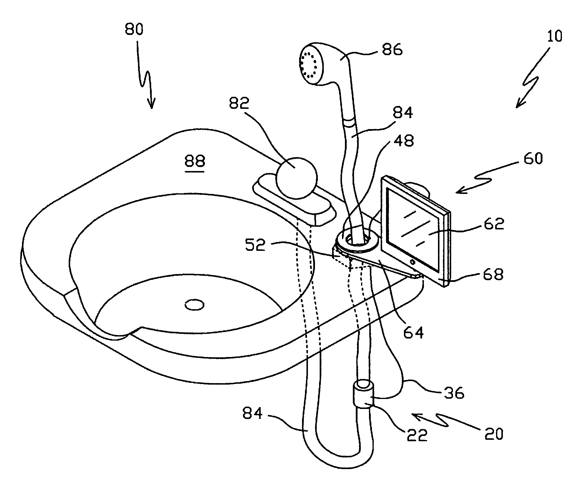
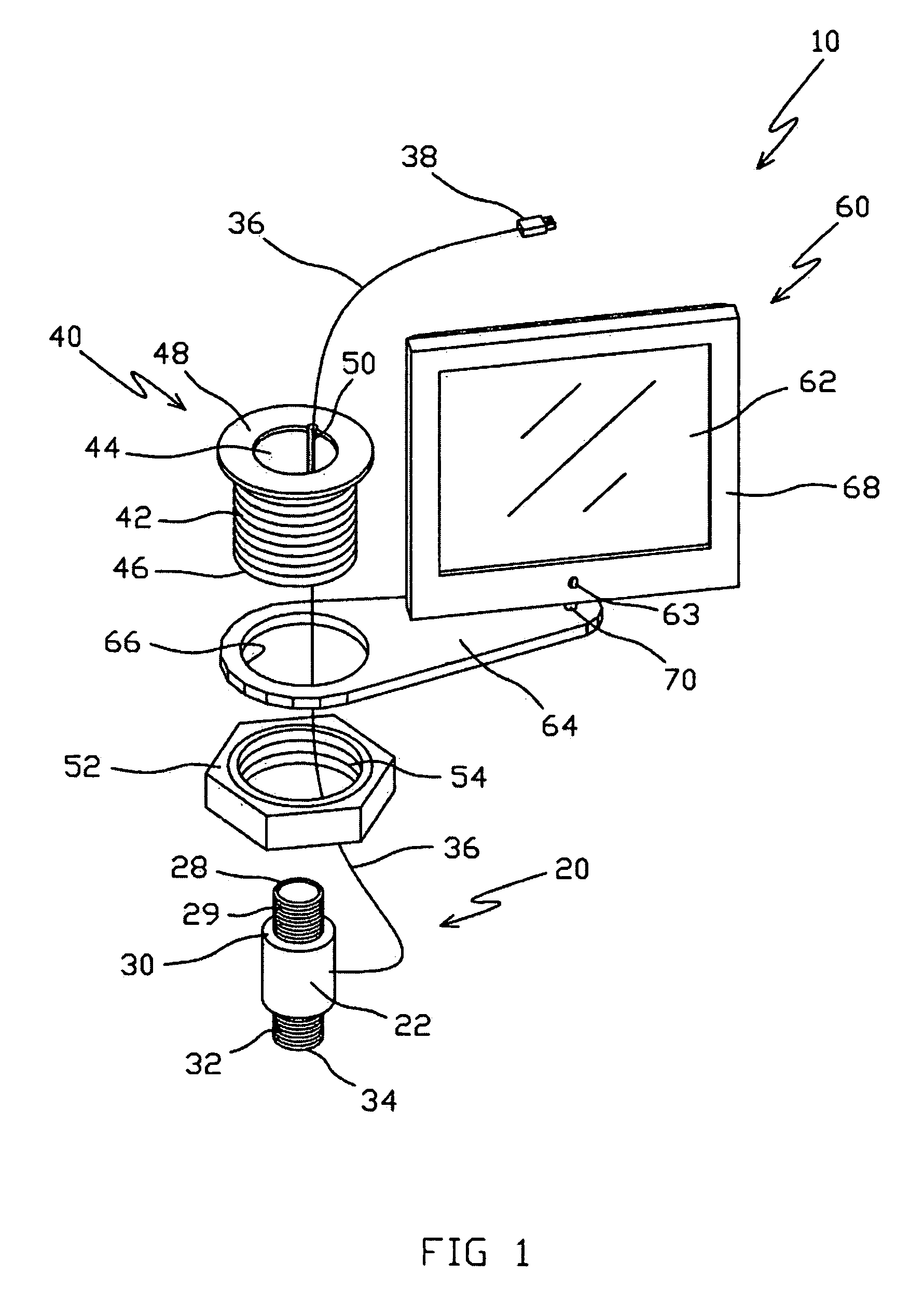
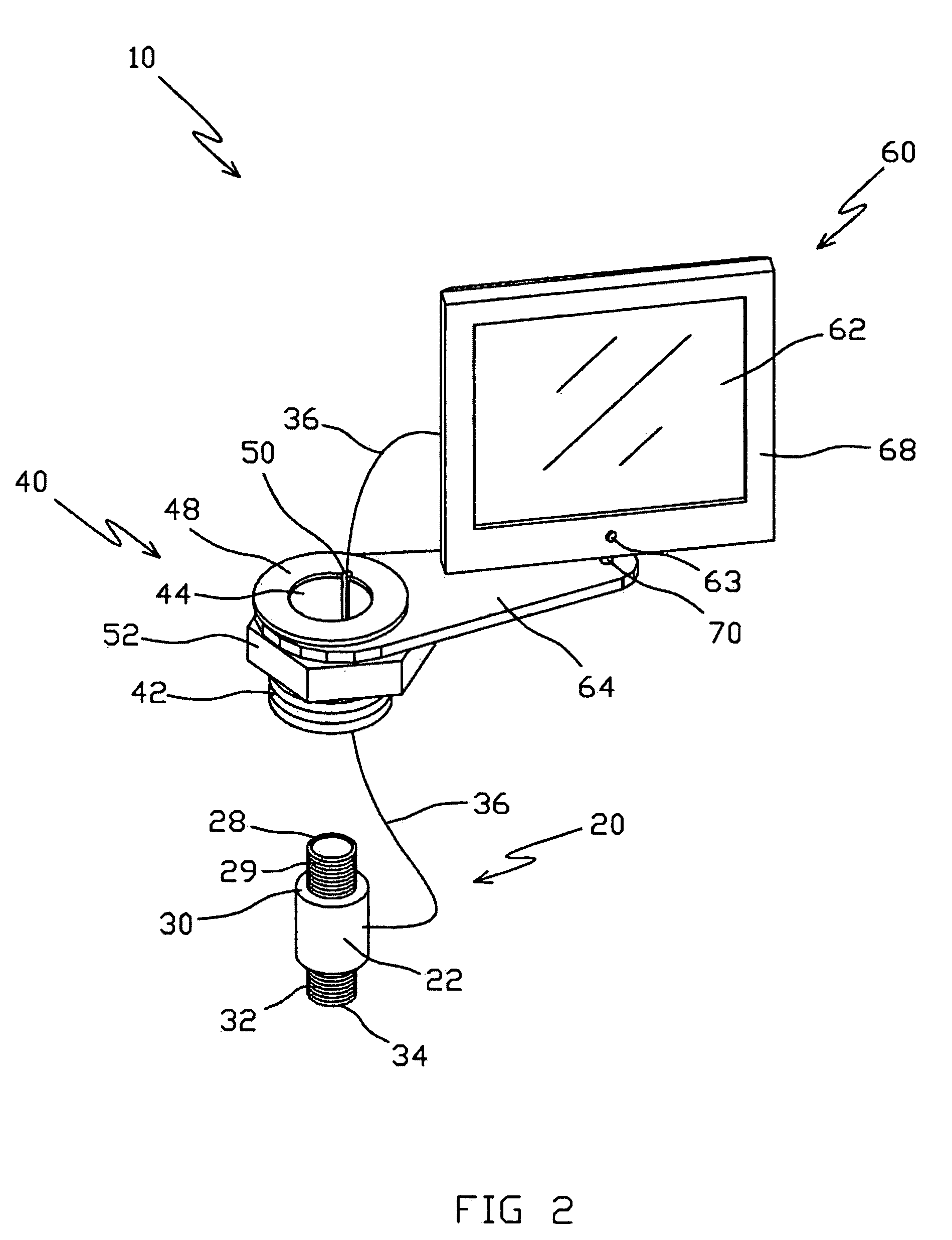
[0032]Referring now to the drawings, where the present invention is generally referred to with numeral 10, it can be observed that it basically includes sensor-coupling unit 20, bushing 40, and display panel assembly 60.

[0033]As shown in FIGS. 1–3, sensor-coupling unit 20 comprises face 22. Extending from face 22 is connecting wire 36, which terminates at connector 38. Connector 38 plugs into port 65 opposite display panel 62 of display panel assembly 60. Male thread 29 outwardly extrudes from face 30 and terminates at edge 28. In the direction opposite of male thread 29, male thread 32 outwardly extrudes from a face, not seen, and terminates at edge 34.

[0034]Bushing 40 comprises face 48 and has internal wall 44 therethrough. Perpendicularly extending from face 48 are male threads 42 that terminate at edge 46. Mounted and secured onto internal wall 44 is channel 50. Channel 50 has cooperative characteristics to snugly receive connecting wire 36. Bushing 40 has cooperative characteri...


PUM


Abstract

An electronic temperature display system that connects directly to a water outlet comprising a sensor coupling unit, bushing, and a display panel assembly. Microprocessor-based circuitry monitors both temperature and the presence or absence of water through the water outlet. The device displays real-time shower temperature on a self-contained unit consisting of a position adjustable display panel. A programmable temperature scorching setting provides protection from scorching by signaling an audible warning tone when the water temperature has gone passed a preset temperature. The device displays true water temperature by monitoring temperature and water conductivity inside the sensor-coupling unit.

Description

OTHER RELATED APPLICATIONS[0001]The present application is a continuation-in-part of U.S. patent application Ser. No. 10 / 784,094, filed on Feb. 23, 2004, now U.S. Pat. No. 7,124,452 which is hereby incorporated by reference.BACKGROUND OF THE INVENTION[0002]1. Field of the Invention[0003]The present invention relates to temperature display systems, and more particularly, to a device used to display real-time temperature of water delivered by a water outlet.[0004]2. Description of the Related Art[0005]Several designs for temperature control systems consist of cumbersome and expensive adaptations that require replacement of existing plumbing systems, including installation of electrical wiring. These modifications are very expensive and time consuming; furthermore, most consumers are not eager to dismantle their walls and / or wall tiles for devices that practically have no market presence or time-tested reliability. If the typical temperature control system were to fail, the user would ...

Claims


Application Information

Patent Timeline
Patent Type & Authority Patents(United States)
IPC IPC(8): E03C1/04
CPCE03C1/055G01K3/005G01K1/143E03C2001/0418
Inventor BAUZA, PEDRO
Owner BAUZA PEDRO
Why Eureka
Try Eureka