Refrigeration plant for parts of installation, which are to be chilled

a technology for refrigeration plants and parts, applied in the direction of superconducting magnets/coils, domestic cooling apparatus, magnetic bodies, etc., can solve the problems of increasing the risk of significant thermal conduction losses, unable to maintain the operating state of the winding which is to be cooled, and generally having to be switched o

Inactive Publication Date: 2007-02-13
SIEMENS AG
View PDF27 Cites 2 Cited by
  • Summary
  • Abstract
  • Description
  • Claims
  • Application Information

AI Technical Summary

Benefits of technology

[0010]It is an object of the present invention to configure the refrigeration plant having the features described in the introduction in such a way that in the event of cooling using a refrigerant that circulates in line parts using a thermosyphon effect, allowing continuous cooling operation without there being any risk of significant thermal conduction losses via the circulating refrigerant.
[0012]The refrigeration plant designed in accordance with the invention therefore includes a plurality of separate regions at which the recondensation of the refrigerant or of a working gas takes place in a thermosyphon system of lines. The associated advantages are in particular that thermal coupling of a correspondingly large number of cold heads is made possible in a simple way. The sufficiently poor thermal conduction in the line sections of the thermosyphon system of lines then allows economic operation with negligible additional introduction of heat even at part-load without all the cold heads installed having to operate simultaneously. This in particular allows a cold head to be replaced, for example for maintenance or repair reasons, while at the same time maintaining the operating temperature at those parts of the superconducting device which are to be cooled with the aid of the remaining cold head(s). Moreover, on account of the branching of line parts, it is possible for the branched line sections to be of sufficiently flexible configuration in order, for example, to allow temperature-induced changes in length, which inevitably arise in the case of cold heads at different temperature levels, in the region of bends, for example, to be mechanically compensated for.
[0013]For example, the line sections which are of poor thermal conductivity may preferably each at least in part be made of a metallic material of poor thermal conductivity or possibly even a plastics material. This makes it possible to achieve not only the desired thermal decoupling of the two cold heads from the parts that are to be cooled via the wall material of the line sections, but also to control any expansion problems.
[0014]Furthermore, the installation that is to be cooled may be located in the interior of a vacuum vessel, with end parts, to which the line sections are thermally coupled, of the cold heads projecting into the vacuum vessel. This makes it possible to limit the undesirable introduction of heat into the region of the installation that is to be cooled.
[0015]It is advantageously possible for the cold heads to have end-side cold surfaces, to which end spaces of the line sections, in which cooling or condensation of the refrigerant takes place, are thermally coupled. This allows a flow of refrigerant to fan out utilizing the desired thermosyphon effect.

Problems solved by technology

In the event of a fault in the refrigeration unit, in particular its cold head, or in the event of the latter having to be repaired or exchanged, however, it is almost impossible to maintain the operating state of the winding which is to be cooled.
On account of the connection of a plurality of cold heads with good thermal conductivity to form the same parts that are to be cooled, however, additional thermal conduction losses caused by a cold head which may be switched off generally have to be accepted.

Method used


Image

  • Refrigeration plant for parts of installation, which are to be chilled
  • Refrigeration plant for parts of installation, which are to be chilled
  • Refrigeration plant for parts of installation, which are to be chilled

Examples


Embodiment Construction

[0022]Reference will now be made in detail to the preferred embodiments of the present invention, examples of which are illustrated in the accompanying drawings, wherein like reference symbols refer to like elements throughout.

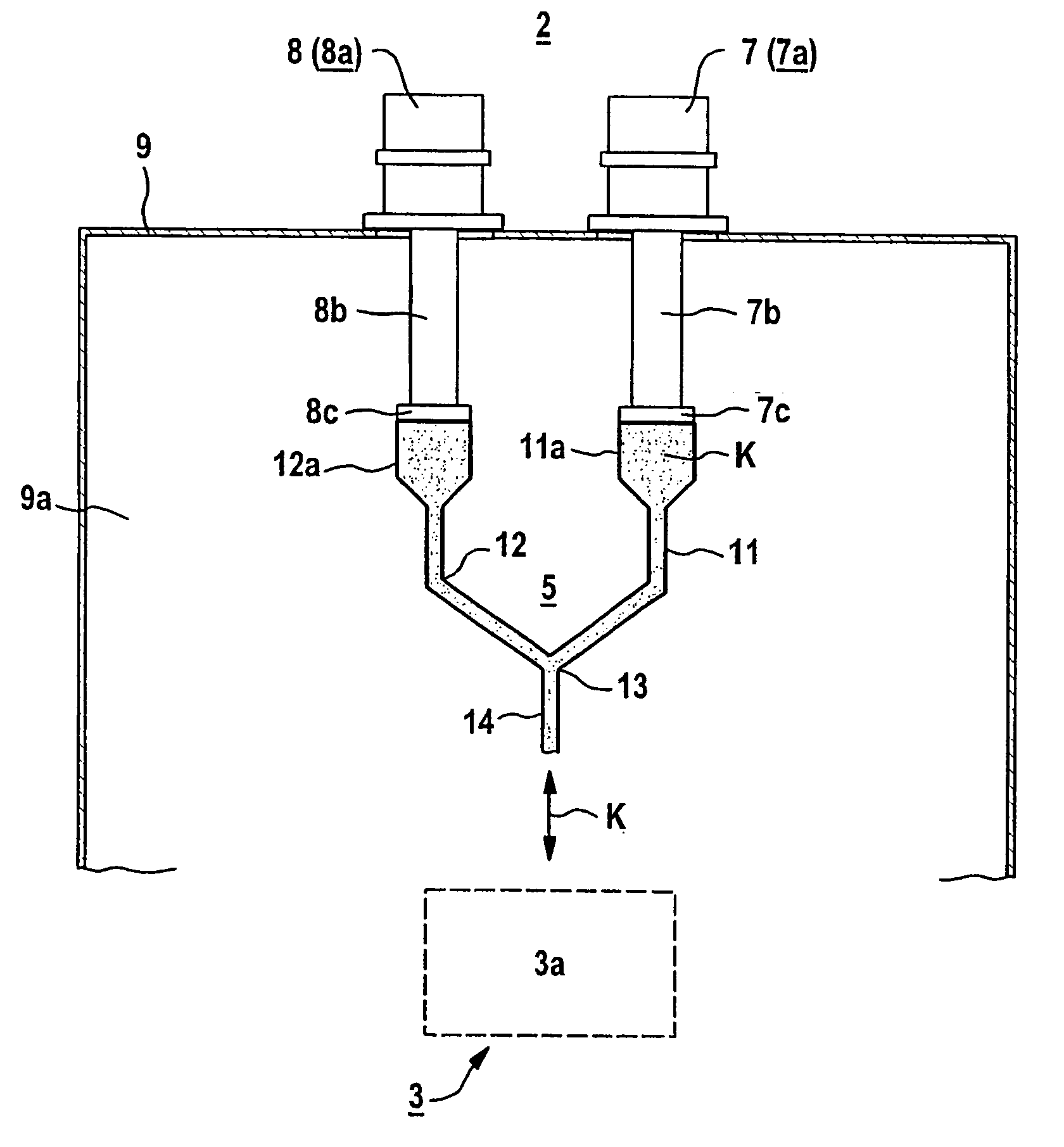
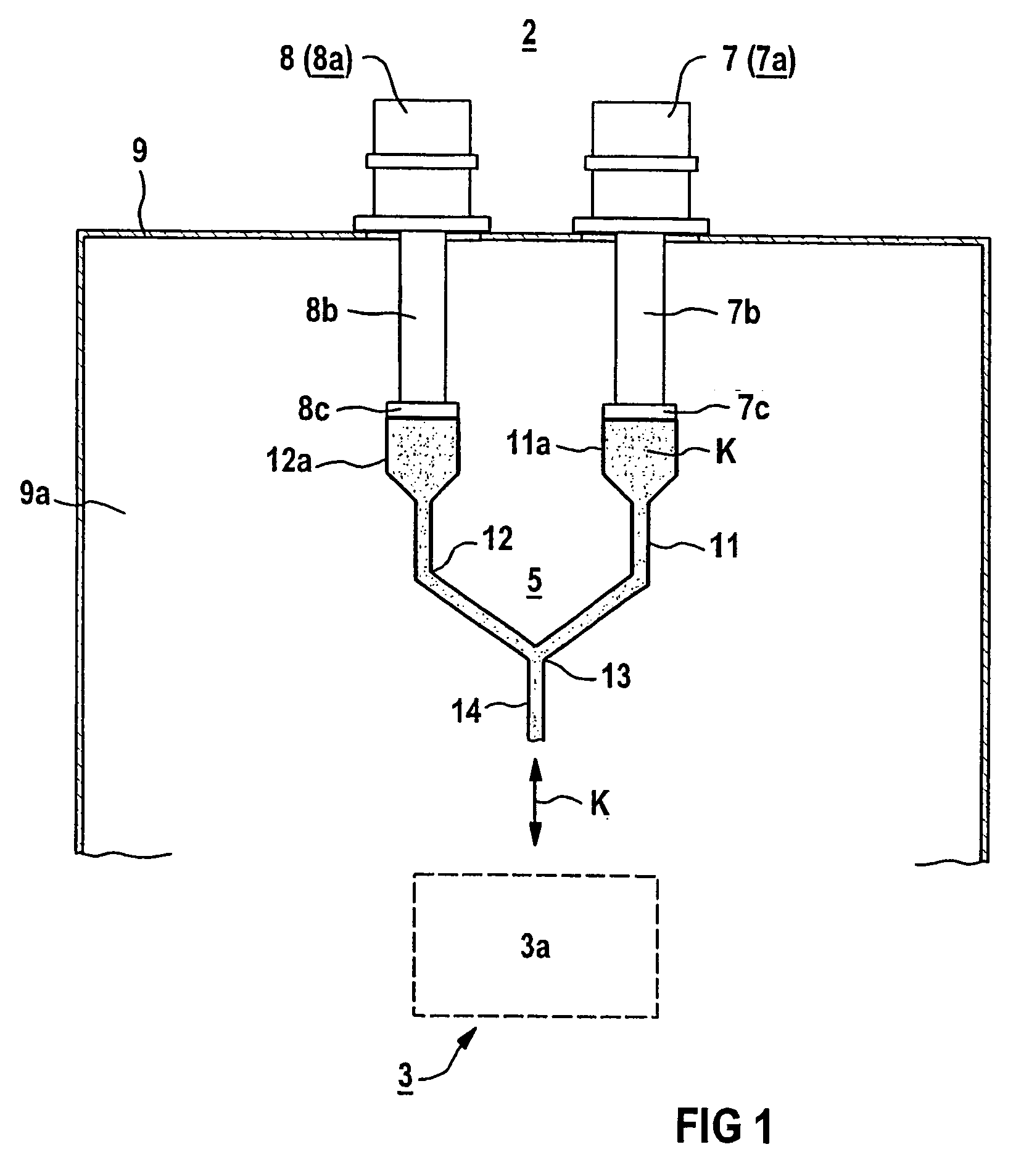
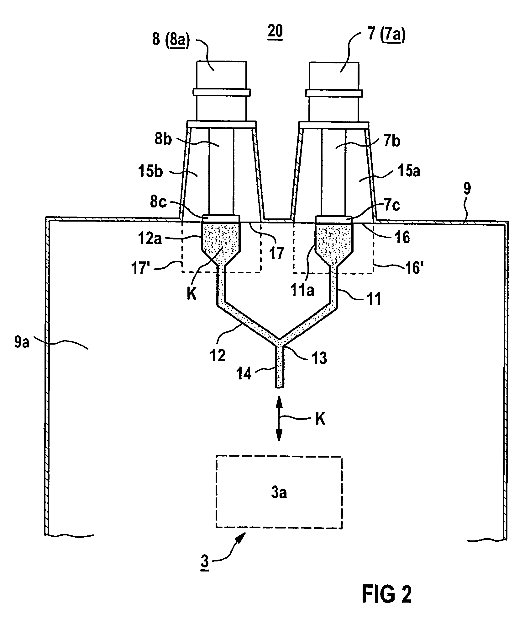
[0023]The refrigeration plant according to the invention can be used wherever a plurality of refrigeration sources are provided for cooling even extensive parts of any desired installation. Their parts which are to be cooled may be metallic or nonmetallic, electrically conductive, in particular superconducting, or also nonconductive. In one specific application, the parts to be cooled are a superconducting winding of an electrical machine (cf. for example the abovementioned WO 00 / 13296 A or U.S. Pat. No. 5,482,919 A) or a superconducting magnet (cf. for example U.S. Pat. Nos. 5,396,206 A or US 6,246,308 B1).

[0024]A further application may be for two cold heads to be operated simultaneously to save time during cooling of the parts of an installation that are to...


PUM

PropertyMeasurementUnit
temperatureaaaaaaaaaa
critical temperatures Tcaaaaaaaaaa
temperatureaaaaaaaaaa

Abstract

A refrigeration plant includes at least two cold heads thermally coupled to parts of a particularly superconducting installation. The parts are to be chilled via a conduit system in which a cooling agent circulates according to a thermosyphon effect. The cold heads are connected in parallel by a forking of the conduit system. Sections of the conduit system, which are positioned between the forking and the cold heads, are configured at least in part so as to be low heat conductive.

Description

CROSS REFERENCE TO RELATED APPLICATIONS[0001]This application is based on and hereby claims priority to German Application No. 102 11 568.0 filed on 15 Mar. 2002, the contents of which are hereby incorporated by reference.BACKGROUND OF THE INVENTION[0002]1. Field of the Invention[0003]The invention relates to a refrigeration plant having a cold head which is thermally coupled, via a system of lines for a refrigerant which circulates in accordance with a thermosyphon effect, to parts of an installation which are to be cooled. A corresponding refrigeration installation is also given by WO 00 / 13296 A.[0004]2. Description of the Related Art[0005]In addition to metallic superconductor materials, such as NbTi or Nb3Sn, which have long been known and have very low critical temperatures Tc and are therefore also referred to as low-Tc superconductor materials or LTS materials, metal-oxide superconductor materials with critical temperatures Tc of over 77 K have been known since 1987. The latt...

Claims


Application Information

Patent Timeline
Patent Type & Authority Patents(United States)
IPC IPC(8): F25D23/12F25B9/00F25B9/14F25B25/00F28D15/00F28D15/02H01F6/04
CPCF25B25/005F28D15/00F25B9/14H01F6/04F25B2400/17F25B2400/06
Inventor FRANK, MICHAELVAN HASSELT, PETER
Owner SIEMENS AG
Why Eureka
Try Eureka