Power tool interface

a tool interface and tool technology, applied in the direction of pulse technique, ignition automatic control, instruments, etc., can solve the problems of large tools, unsatisfactory approaches, and bulky tools

Active Publication Date: 2007-02-13
C P ELECTRONICS
View PDF8 Cites 179 Cited by
  • Summary
  • Abstract
  • Description
  • Claims
  • Application Information

AI Technical Summary

Benefits of technology

[0004]The present invention is directed to an apparatus for controlling a power supply delivering power to a DC powered tool. An interface is connected between the DC power supply and the DC tool wherein the interface is configured to read signals from the tool and control the power supplied by the power supply to run, brake, reverse or jog the tool. A microprocessor is connected to the interface programmed to provide a specific power in response to the signals from the tool read by the interface. The interface includes a number of field effect transistors. They are PFET1, PFET2, NFET1, and NFET2.

Problems solved by technology

This is very expensive.
Also, this approach often has been unsatisfactory because the measuring and controlling are not direct enough.
These attempts often lead to large, bulky tools.

Method used


Image

  • Power tool interface
  • Power tool interface
  • Power tool interface

Examples


Embodiment Construction

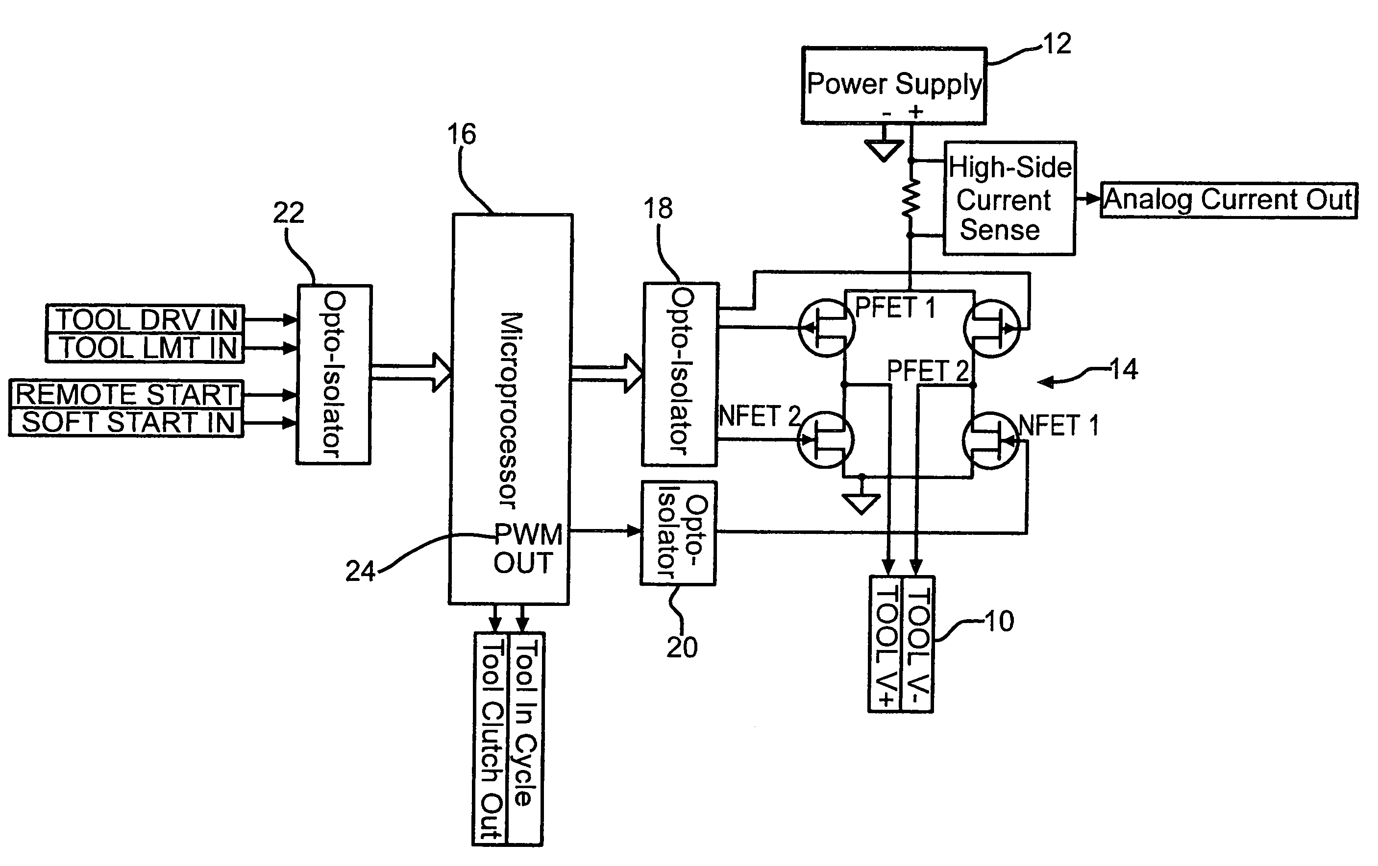
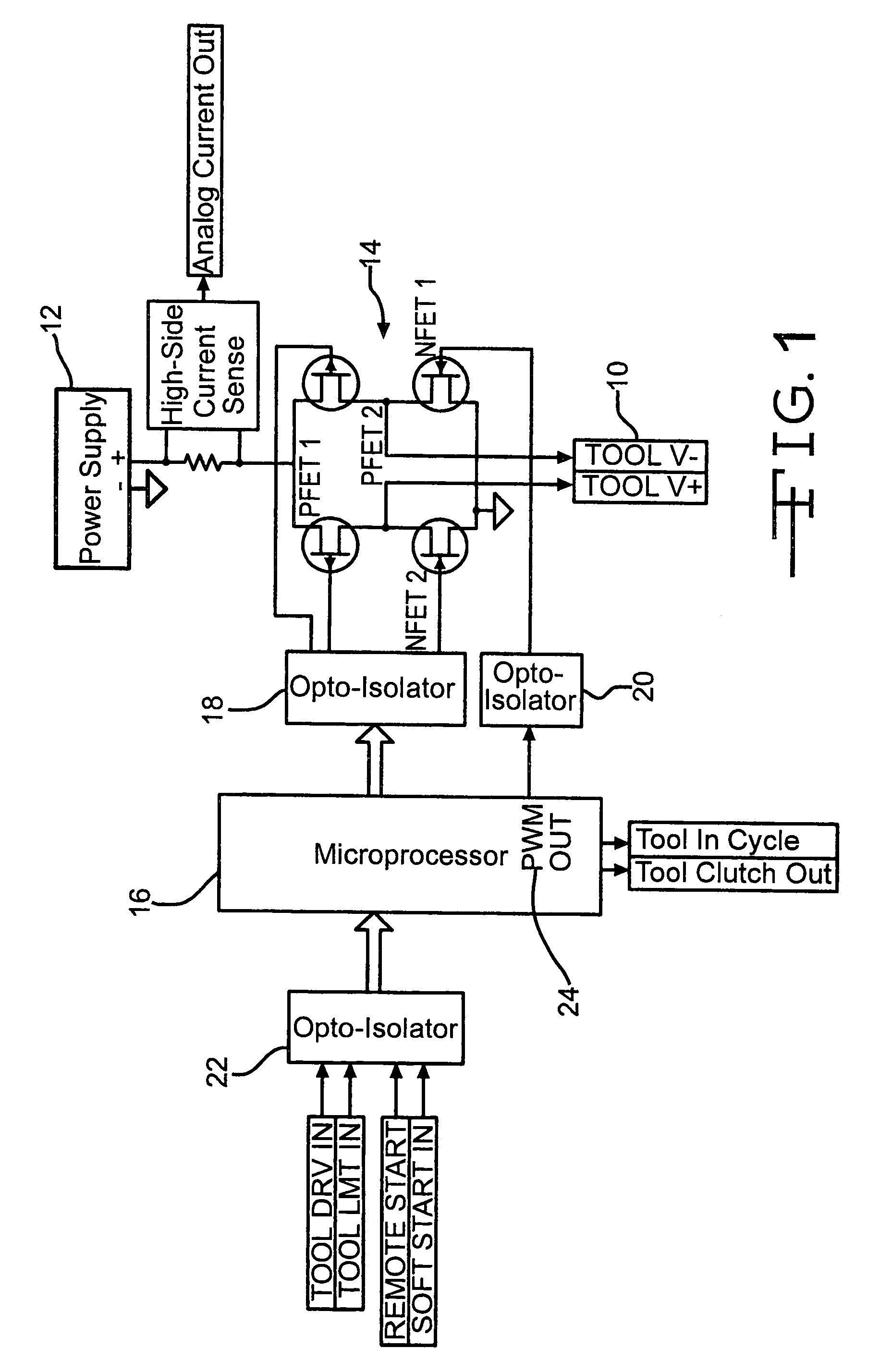
[0008]FIG. 1 is a block diagram for the control circuit of this invention providing power to DC power tool 10. DC power supply 12 provides power to tool 10 through interface 14. Microprocessor 16 is connected to interface 14 through opto-isolator 18 and opto-isolator 20. Interface 14 includes field effect transistors PFET1, PFET2, NFET1 and NFET2.

[0009]When tool 10 is at rest, microprocessor 16 will turn on PFET1 with all of the other FETs off. The microprocessor is programmed, when the tool is at rest, to allow PFET1 to conduct by grounding its gate and placing all remaining FETs in their non-conducting states. This action provides a positive voltage to tool 10 so that signals can be read by the microprocessor. However, since NFET1 is off there is no complete path to ground. Therefore tool 10 cannot run. The microprocessor is programmed to control the gate voltages of PFET1 and NFET1. As a result, PFET1 and NFET1 provide power to the tool allowing the tool to run in a forward or cl...


PUM


Abstract

This interface is an apparatus for controlling a power supply delivering power to a DC powered tool. The interface is connected between the DC power supply and the DC tool wherein the interface is configured to read signals from the tool and control the power supplied by allowing the power supply to run, brake, reverse or jog the tool. A microprocessor is connected to the interface programmed to provide a specific power in response to the signals from the tool read by the interface. The interface includes a number of field effect transistors. They are PFET1, PFET2, NFET1, and NFET2.

Description

TECHNICAL FIELD OF THE INVENTION[0001]The interface of this invention is a circuit that allows a user to take a standard power supply and use it to control a DC brush or brush-less tool. This interface has the ability to read the signals from the tool and manipulate the voltage supplied by the power supply in order to run and brake the tool properly.BACKGROUND OF THE INVENTION[0002]This invention relates to a process and apparatus that controls the power delivered to a tool without the use of complicated components. Preciseness and consistency are very important to mass production operations, such as automobile assembly plants. Power tool driving threaded fasteners must be consistent. Industry typically incorporates controlling devices into the power tool. This is very expensive. Also, this approach often has been unsatisfactory because the measuring and controlling are not direct enough. These attempts often lead to large, bulky tools.[0003]For example, in a typical power tool, an ...

Claims


Application Information

Patent Timeline
Patent Type & Authority Patents(United States)
IPC IPC(8): E21B3/00G05B24/02H03H1/00
CPCH02P7/0044H02P7/29H03K17/785H03K17/6872H03K17/0822H02P7/04
Inventor LYSAGHT, RICHARD G.
Owner C P ELECTRONICS
Why Eureka
Try Eureka