Air spring and shock absorber assembly for use in suspension systems

a technology of air spring and shock absorber, which is applied in the direction of shock absorbers, mechanical equipment, transportation and packaging, etc., can solve the problems of increasing noise and vibration transmission, and affecting the transmission of vibration through

Inactive Publication Date: 2007-02-13
LINK MFG
View PDF25 Cites 27 Cited by
  • Summary
  • Abstract
  • Description
  • Claims
  • Application Information

AI Technical Summary

Benefits of technology

[0009]The air spring includes an end cap which is positioned above and which is operably secured to the rod end mount of the shock absorber. The air spring includes a flexible bellows having upper and lower ends with the upper end of the bellows being sealably secured to the end cap. The air spring also includes an air spring piston which has upper and lower ends with the piston having a central bore extending therethrough between its upper and lower ends. The piston also has a reduced diameter portion at its upper end. The shock absorber body is received by the central bore in the piston with at least one projection on the shock absorber body engaging the lower end of the piston to prevent downward movement of the air spring piston with respect to the shock absorber body.
[0014]Still another object of the invention is to provide an air spring and shock absorber assembly including a novel means for connecting the lower end of the air spring bellows to the upper end of the air spring piston so that the piston may be removed from the assembly and substituting a different piston without destroying the lower crimp ring which connects the bellows to the piston.
[0016]It is a further object of the invention to provide an air spring and shock absorber assembly which permits the air spring piston to be easily exchanged for a piston with a different profile yielding a different spring rate.

Problems solved by technology

Another consideration in air spring and shock absorber assemblies of the prior art is that there is a pre-loading on the shock absorber end mounts which causes vibration transmission therethrough.
In most assemblies of the prior art, the lifting force of the air spring is being transmitted through the shock absorber end mounts which pre-loads them with a very high force and makes noise and vibration transmission much more prevalent.

Method used


Image

  • Air spring and shock absorber assembly for use in suspension systems
  • Air spring and shock absorber assembly for use in suspension systems
  • Air spring and shock absorber assembly for use in suspension systems

Examples


Embodiment Construction

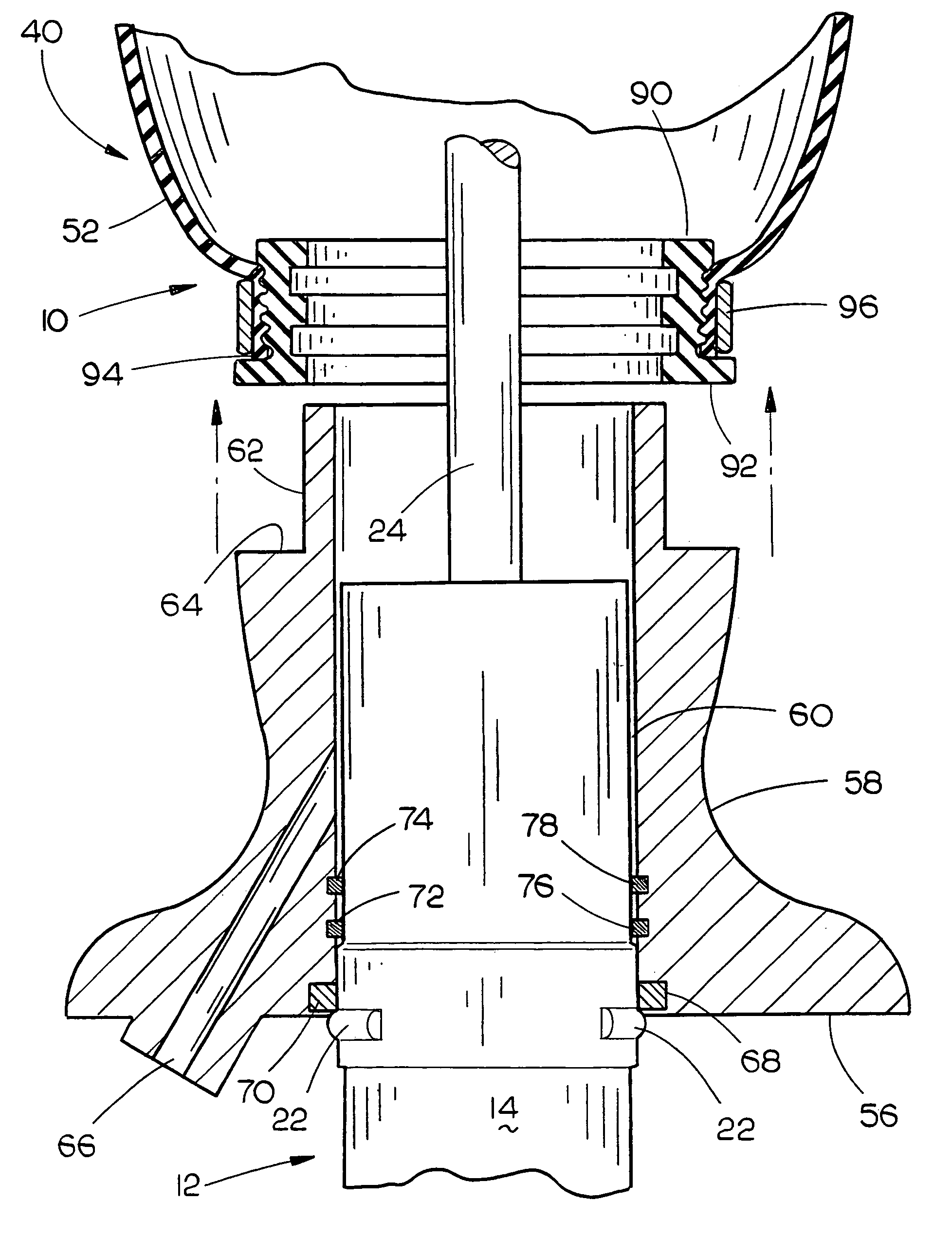
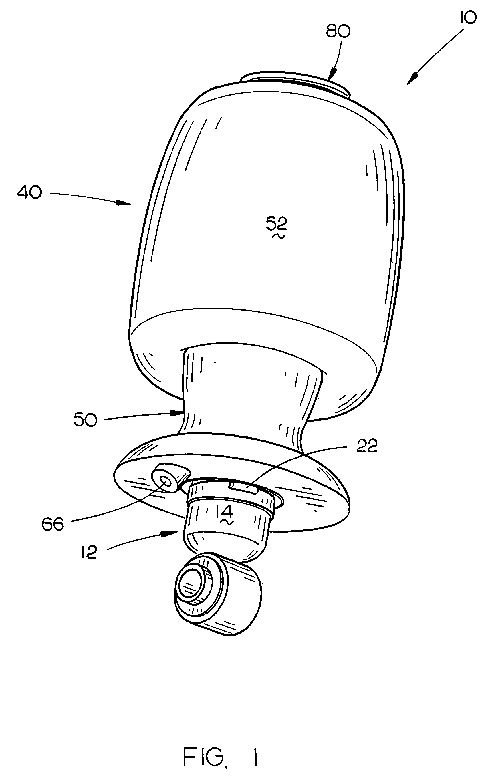
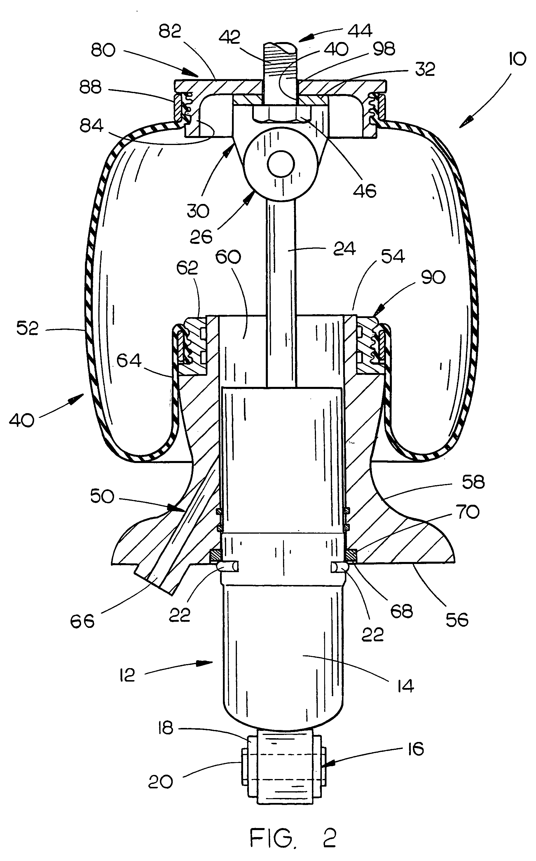
[0022]The numeral 10 refers to the air spring and shock absorber assembly of this invention which is designed for air-suspended vehicles or for vehicle cab suspensions. One end of the assembly is operably secured to the vehicle frame with the other end thereof operably secured to the vehicle axle or control arm associated therewith if the assembly is used in a vehicle suspension system. If the assembly is used in a vehicle cab suspension, one end of the assembly will be secured to the vehicle cab and the other end will be secured to the frame of the vehicle.

[0023]Assembly 10 includes a conventional shock absorber 12 having a body 14 which has a base end mount 16 provided at the lower or base end thereof. Mount 16 includes a conventional rubber or resilient bushing 18 having a metal sleeve 20 positioned thereon. The outer surface of body 14 has a plurality of radially spaced-apart protrusions or projections 22 extending outwardly therefrom above the base end thereof. Rod 24 slidably ...


PUM


Abstract

An air spring and shock absorber unit for use in vehicle suspension systems or cab suspension systems comprising a shock absorber mounted within an air spring. The lower end of the air spring bellows is attached to the air spring piston in such a manner which enables the lower end of the bellows to be disconnected from the air spring piston without damaging the crimp ring which connects the bellows to the piston.

Description

BACKGROUND OF THE INVENTION[0001]1. Field of the Invention[0002]This invention relates to an air spring and shock absorber assembly for use in suspension systems and more particularly to an air spring and shock absorber assembly for use in vehicle suspension systems. Even more particularly, the invention relates to an air spring and shock absorber assembly wherein the lower end of the air spring bellows may be disconnected from the air spring piston without removing, i.e., destroying, the lower crimp ring or clamping ring, thereby enabling a substitute air spring piston to be installed in the assembly so that the characteristics of the assembly may be changed.[0003]2. Description of the Related Art[0004]Many different types of air spring and shock absorber assemblies have been previously provided for use in suspension systems such as vehicle suspension or cab suspension systems. For example, see U.S. Pat. Nos. 5,649,692; 6,443,436; and 6,715,744. Each of the assemblies of the above-...

Claims


Application Information

Patent Timeline
Patent Type & Authority Patents(United States)
IPC IPC(8): F16F9/04F16F9/43
CPCF16F9/057F16F9/0463B60G2202/314B60G2206/424
Inventor VANDE BRAKE, KENNETH R.NIBBELINK, JEFFREY S.
Owner LINK MFG
Why Eureka
Try Eureka