Finisher with increased conveyance speed

a finishing machine and speed technology, applied in the field of image forming system, can solve the problems of deterioration of the overall image forming system efficiency, reduced finishing efficiency, complicated control, etc., and achieve the effect of high speed processing, reduced occurrence rate, and simplified control

Active Publication Date: 2007-02-13
KONICA MINOLTA BUSINESS TECH INC
View PDF9 Cites 20 Cited by
  • Summary
  • Abstract
  • Description
  • Claims
  • Application Information

AI Technical Summary

Benefits of technology

[0038]In an image forming system composed of an image forming apparatus connected with a plurality of finishers, standardized implementation of sheet conveyance control as the entire system is enabled according to any one of (18) through (21) and (23). This arrangement ensures simplified control, reduces the rate of occurrence of such a trouble as jamming and allows high speed processing in the finisher.
[0039]In the finisher of the preceding stage of the image forming system connected with a plurality of finishers, the structure according to any one of (19), (21) and (22) allows the finisher of the succeeding stage to perform smooth conveyance of sheet, even when sheet is ejected at various ejection speeds in conformity with processing modes.
[0040]Even when the function or model has been changed in the finisher of the preceding stage, this arrangement eliminates the need of changing the control section of the finisher of the succeeding stage; hence it removes the necessity of developing a new model devoid of improved performances and minimizes the maintenance loads.

Problems solved by technology

When designing an image forming system equipped with a plurality of finishers, control will become complicated if each finisher is provided with the conveyance speed control function as in Official Gazette of Japanese Patent Tokkaihei 5-16569, and sheet conveyance control is separately carried out.
Such a trouble as jamming is likely to occur and finishing efficiency is reduced, with the result that the efficiency of the overall image forming system will be deteriorated.
However, such information is not sufficient for effective sheet conveyance control in the finisher and high speed processing in the finisher.
This raises the problem of increased servicing loads.

Method used


Image

  • Finisher with increased conveyance speed
  • Finisher with increased conveyance speed
  • Finisher with increased conveyance speed

Examples


Embodiment Construction

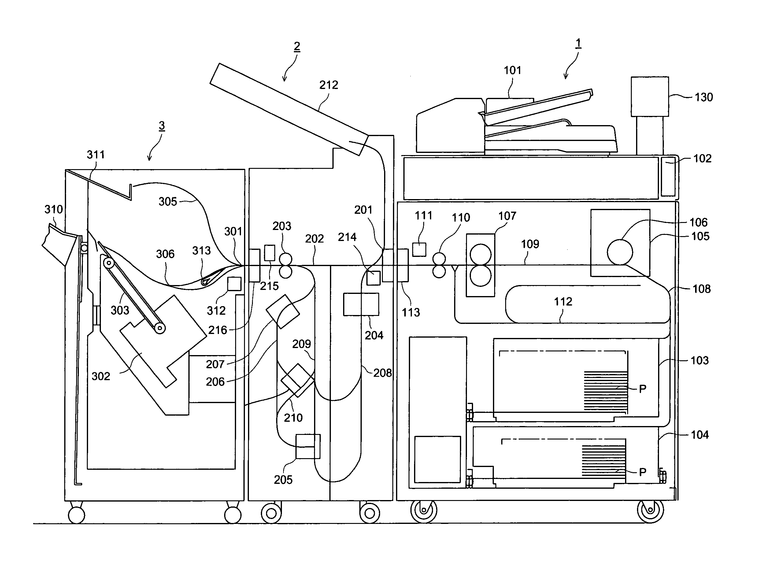
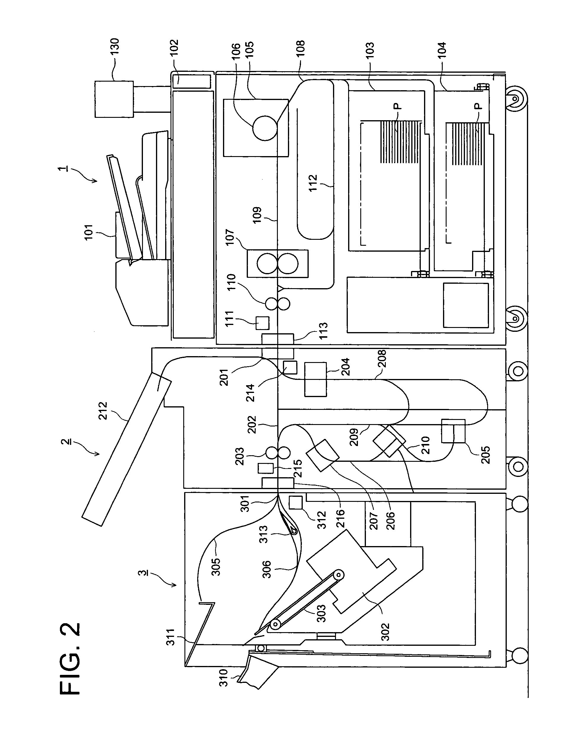
[0047]FIG. 2 is an overall diagram representing an image forming system as an embodiment of the present invention. This image forming system is composed of an image forming apparatus 1, first finisher 2 and second finisher 3.

[0048]An automatic document conveyance apparatus 101 and an image read apparatus 102 are mounted on the top of the image forming apparatus 1, and a printer is located on the lower portion of the image forming apparatus 1.

[0049]In the printer, numerals 103 and 104 denote sheet store sections for sheet P. It contains a photoconductor 106. An image is formed on sheet P in an image forming section 105 for forming an image on the sheet P by the electrophotographic process, and the formed image is fixed on sheet P by the fixing apparatus 107.

[0050]An image is formed on the sheet P supplied by a sheet store section 103 or 104. The sheet P with an image formed thereon is ejected from the ejection port 113 by an ejection roller 110.

[0051]Sheet conveyance paths include a ...


PUM


Abstract

An image forming system includes: an image forming apparatus capable of conveying a recording sheet at a predetermined speed; at least one finisher capable of conveying the sheet eject from the image forming apparatus at a prescribed speed to process the sheet; and a controller for changing a conveyance speed of the recording sheet in the finisher to be higher than that of the sheet in the image forming apparatus.

Description

BACKGROUND OF THE INVENTION[0001]The present invention relates to an image forming system composed of an image forming apparatus connected with a finisher for conducting such processing as punching, folding, stapling and shifting.[0002]An image forming system connected with a finisher for conducting such processing as punching, folding, stapling and shifting to sheet with an image formed thereon is widely used as a system configured on the basis of a high speed image forming apparatus such as an image forming apparatus based on electrophotographic technology.[0003]In the finisher, processing such as folding and stapling is carried out to sheet, which is temporarily stopped. Accordingly, to prevent collision of the sheets of paper conveyed one after another, the conveyance speed is increased immediately before and after a processing station, thereby ensuring a wide space between sheets of paper (Official Gazette of Japanese Patent Tokkaihei 5-16569). When such control is used, a sens...

Claims


Application Information

Patent Timeline
Patent Type & Authority Patents(United States)
IPC IPC(8): B65H29/22B42B4/00B42C1/12G03G15/00B65H5/34B65H33/04
CPCB65H5/34G03G15/6529G03G2215/00949
Inventor ANZAI, EIJIHIRATA, TETSUONAKAMICHI, MOTOKIKATO, NORISHIGEOGUSHI, TAKEHIROSAITSU, YASUSHI
Owner KONICA MINOLTA BUSINESS TECH INC
Why Eureka
Try Eureka