Rotating tool with a clamping shank

Inactive Publication Date: 2007-02-13
REINER QUANZ
View PDF10 Cites 1 Cited by
  • Summary
  • Abstract
  • Description
  • Claims
  • Application Information

AI Technical Summary

Benefits of technology

[0004]The object on which the present invention is based is to improve a tool of the type mentioned, in the region of the clamping shank, in

Problems solved by technology

This makes very firm clamping of the associated clamping chuck necessary, in order to avoid slipping of the tool, along with the adverse consequences, such as the formation of scores and chips on the circumferential surface of the shank.
If clamping is not sufficiently firm, in practice, there is very often slipping of the tool in the clamping chuck.
However, since the clamping surfaces are very n

Method used


Image

  • Rotating tool with a clamping shank
  • Rotating tool with a clamping shank
  • Rotating tool with a clamping shank

Examples


Embodiment Construction

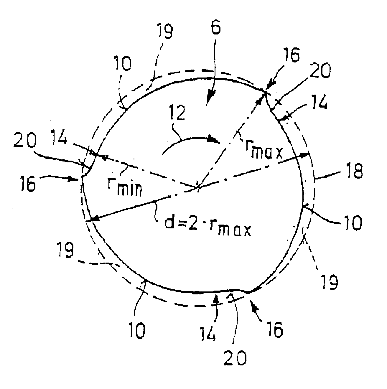
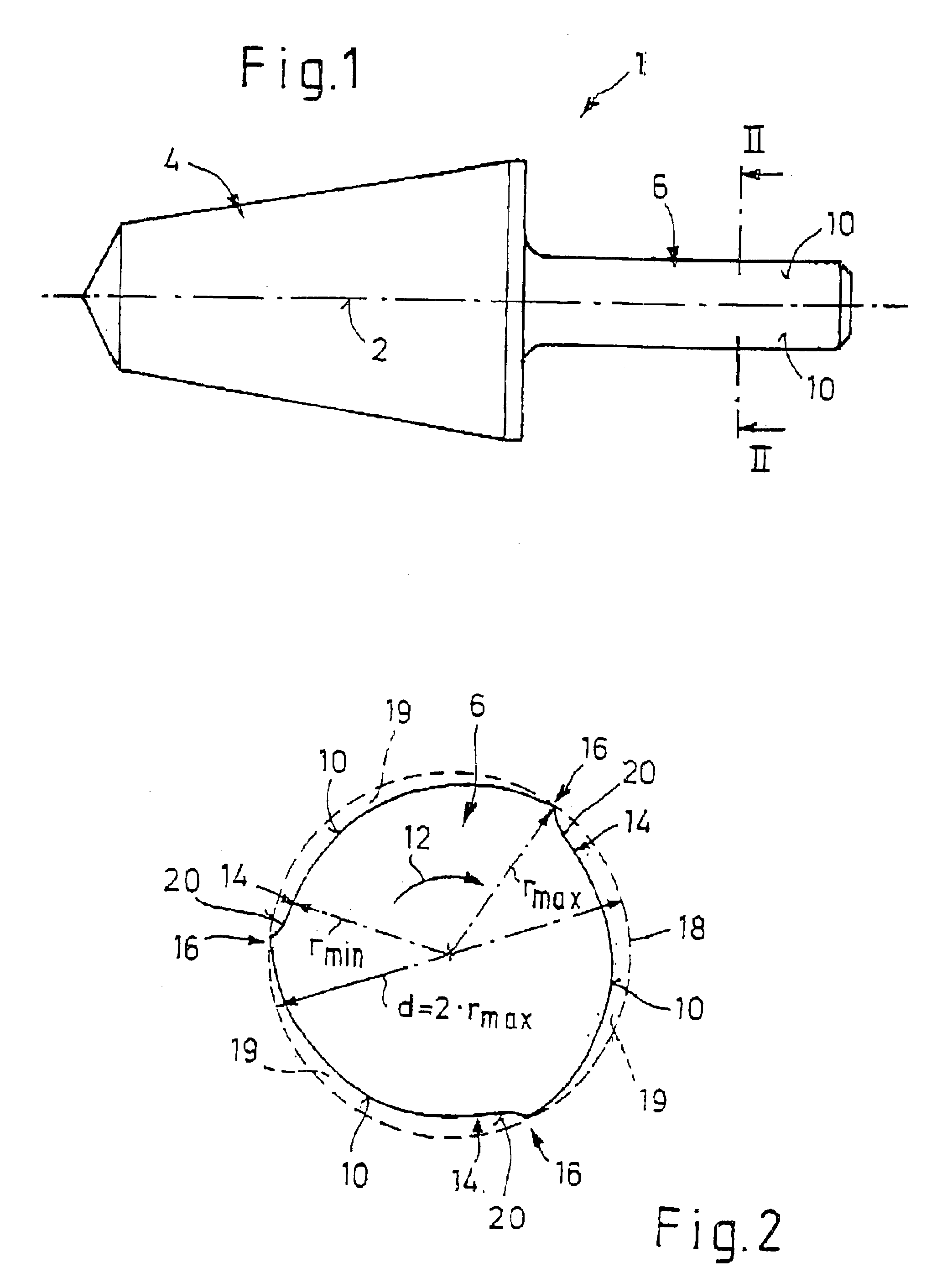
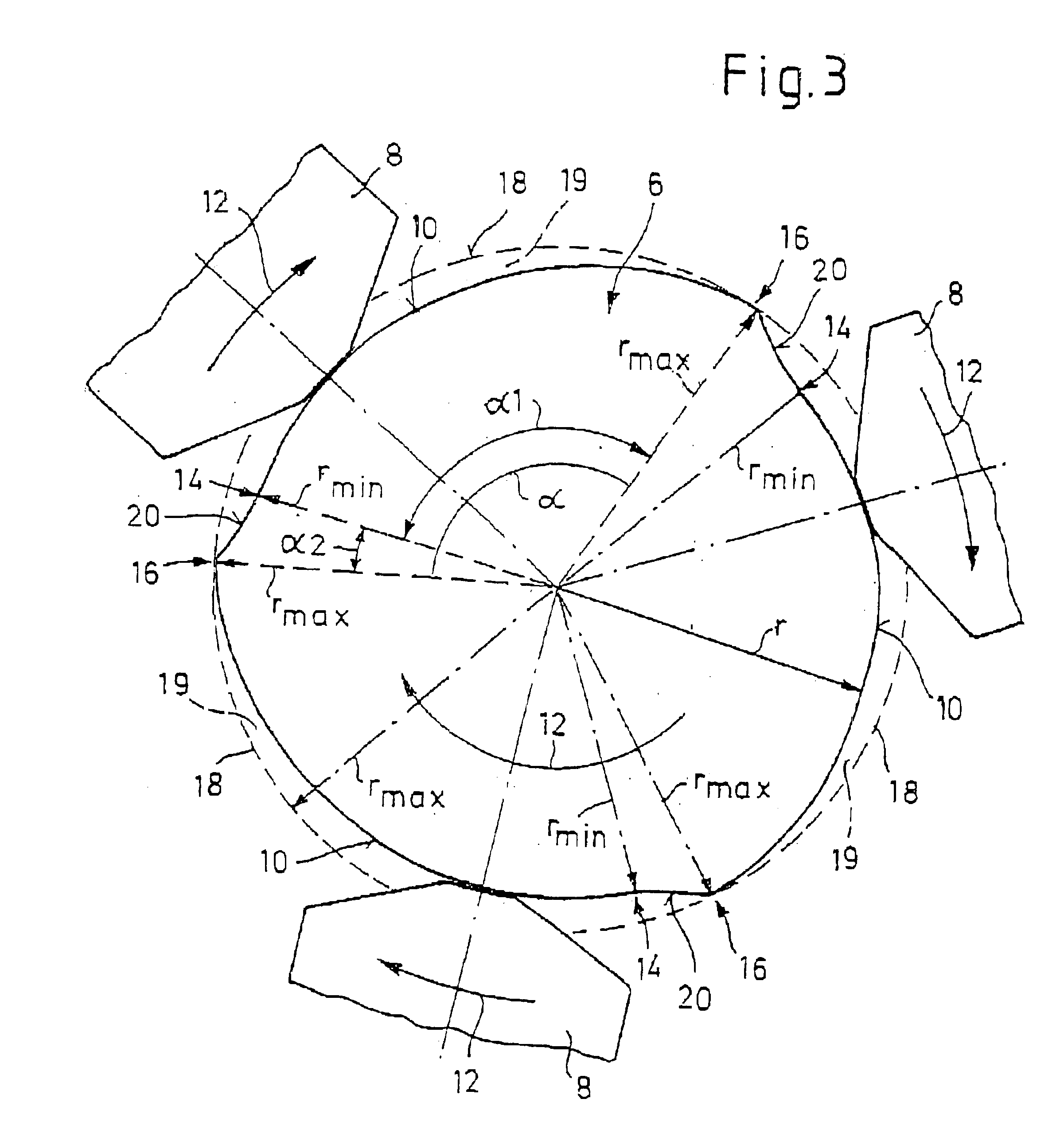
[0014]FIG. 1 illustrates by way of example a tool 1 which consists of a working part 4 to be driven in rotation about an axis of rotation 2 and of an axially adjoining clamping shank 6. The working part 4 is designed, in particular, for cutting machining, for example as a drill, milling cutter, countersink, deburrer or the like. FIG. 1 illustrates by way of example an essentially conical version as what may be referred to as a boring drill, but it may also be, for example, a step drill or any other type of tool. The clamping shank 6 is inserted, for rotational drive, into a clamping chuck of a drive machine which is not illustrated. Depending on the number n of clamping jaws 8 (see FIG. 3) of the respective clamping chuck, the clamping shank 6 has a corresponding number n of clamping surfaces 10 for supporting one of the clamping jaws 8 in each case. Reference is made, in this respect, to the sectional illustrations in FIGS. 2 and 3.

[0015]As may also be gathered from FIGS. 2 and 3, ...


PUM

PropertyMeasurementUnit
Fractionaaaaaaaaaa
Fractionaaaaaaaaaa
Fractionaaaaaaaaaa

Abstract

A rotating tool such as a drill, a milling cutter, a countersink, a deburrer and the like, including a working part, which is driven in rotation about an axis of rotation for cutting machining, and also including an axially adjoining clamping shank for insertion into a clamping chuck of a drive machine. The clamping shank is provided with a number of clamping surfaces on its outer circumference for supporting a clamping jaw of the clamping chuck. The clamping shank has a shank radius in the region of each clamping surface which, as seen in a predetermined direction of rotation of the tool, rises from a minimum shank radius to a maximum shank radius as it passes over a range of angle of rise.

Description

TITLE OF THE INVENTIONBACKGROUND OF THE INVENTION[0001]The present invention relates to a rotating tool, in particular a drill, milling cutter, countersink, deburrer or such like cutting tool, consisting of a working part to be driven in rotation about an axis of rotation and designed, in particular, for cutting machining and of an axially adjoining clamping shank for insertion into a clamping chuck of a drive machine, the clamping shank having, on its outer circumference, a number n≧2 of clamping surfaces for supporting a clamping jaw of the clamping chuck in each case.[0002]In tools of this type, in particular in twist drills and the like, it is known, in the first place, to design the clamping shank cylindrically, that is to say with a circular cross section. This makes very firm clamping of the associated clamping chuck necessary, in order to avoid slipping of the tool, along with the adverse consequences, such as the formation of scores and chips on the circumferential surface ...

Claims


Application Information

Patent Timeline
IPC IPC(8): B23B51/02B23B31/00
CPCB23B31/005Y10T407/1946Y10T408/907B23B2231/0244
Inventor QUANZ, REINER
Owner REINER QUANZ
Why Eureka
Try Eureka