
Method of manufacturing electrolyzer unit, and method and system for welding electrolyzer unit and electrolyzer unit rib

a manufacturing method and technology for electrolyzer units, applied in the manufacture of tools, welding/soldering/cutting articles, electrolysis components, etc., can solve the problems of difficult performance of cooling metal measures and straining of reserved metals, and achieve the effect of eliminating thermal distortions during the welding process

Inactive Publication Date: 2007-02-13
FUJITA WORKS +1
View PDF31 Cites 2 Cited by
  • Summary
  • Abstract
  • Description
  • Claims
  • Application Information

AI Technical Summary

Benefits of technology

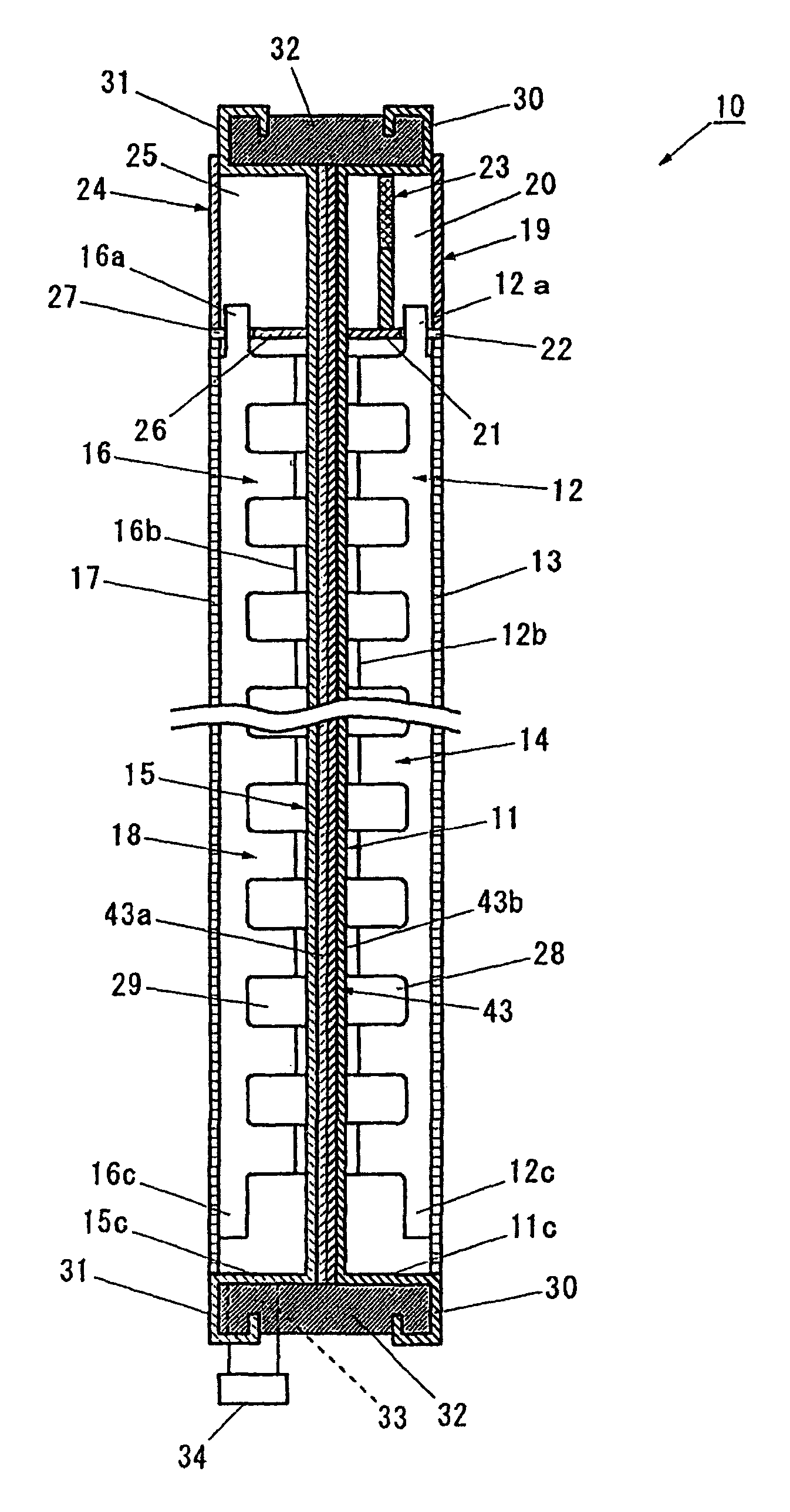
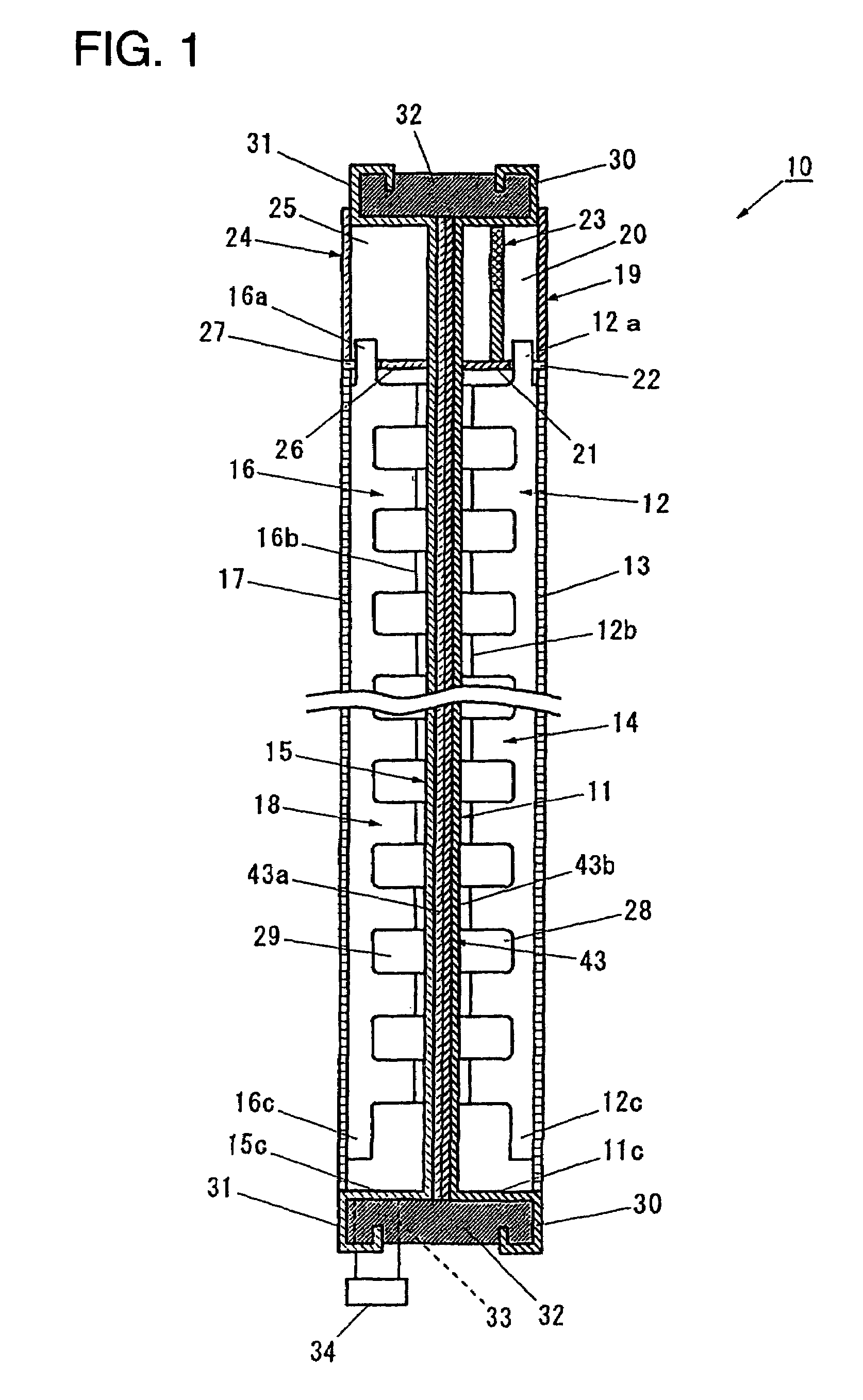
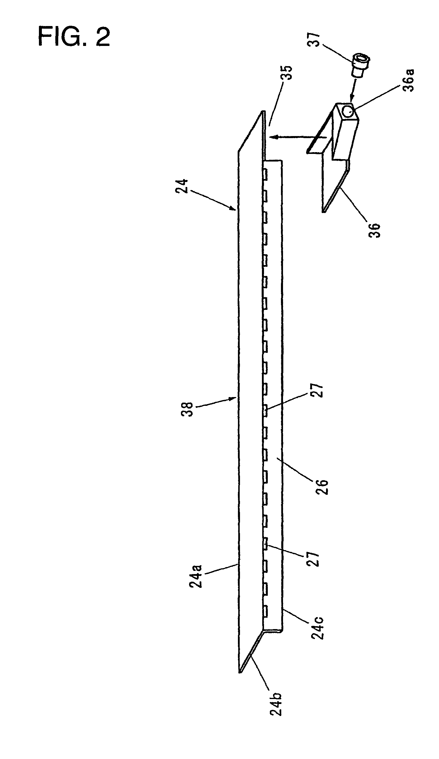
The patent describes a method of manufacturing an electrolyzer unit by arranging a partition member on a front surface of a first pan with flange portions and welding it to the flange portions to form a gas-liquid separation chamber. The method also includes arranging a plurality of first ribs on the front surface of the first pan, arranging a plurality of clad plates on a back surface of the first pan at positions corresponding to the ribs, putting a back surface of the second pan over the back surface of the first pan, and arranging a plurality of second ribs on the front surface of the second pan. The method allows for reliable detection of welded portions, reduces the number of welding steps, and enables individual inspection and adjustment of the panels. The simultaneous welding of the partition member and the flange portions of the panels can be performed, and the method can be carried out using a capacitor type projection welding method.

Problems solved by technology

However, even before the frame members are inserted, it is sufficiently possible to suppress thermal strains of the pan by taking such measures as “reverse straining” and “cooling metal” (if the first pan and the second pan are fixed together by inserting the frame members, the reserve straining and cooling metal measures become difficult to perform as the other pan interferes with the operation).

Method used


Image

  • Method of manufacturing electrolyzer unit, and method and system for welding electrolyzer unit and electrolyzer unit rib
  • Method of manufacturing electrolyzer unit, and method and system for welding electrolyzer unit and electrolyzer unit rib
  • Method of manufacturing electrolyzer unit, and method and system for welding electrolyzer unit and electrolyzer unit rib

Examples


example 1

(1) Construction of Cathode Rib

[0215]Material→Nickel[0216]Thickness→1.5 mm[0217]Number of projections→One per pan contact portion[0218]Height of projections→0.8 mm[0219]Diameter of projections→7.0 mm

(2) Construction of Cathode Pan[0220]Material→Nickel[0221]Thickness→1.0 mm

(3) Construction of Clad Plate[0222]Material→Nickel layer+titanium layer[0223]Thickness of nickel layer→1.0 mm[0224]Thickness of titanium layer→1.0 mm

(4) Construction of Anode Pan[0225]Material→Titanium[0226]Thickness→1.0 mm

(5) Construction of Anode Rib[0227]Material→Titanium[0228]Thickness→1.5 mm[0229]Number of projections→Zero per pan contact portion

(6) Welding Condition[0230]Weld voltage→360 V[0231]Pressing force→440 kg[0232]Transformation ratio→30:1

(7) Tensile Strength After Welding[0233]504–647 kg

example 2

(1) Construction of Cathode Rib

[0234]Material→Nickel[0235]Thickness→1.5 mm[0236]Number of projections→One per pan contact portion[0237]Height of projections→0.8 mm[0238]Diameter of projections→7.0 mm

(2) Construction of Cathode Pan[0239]Material→Nickel[0240]Thickness→1.0 mm

(3) Construction of Clad Plate[0241]Material→Stainless steel layer (SUS316)+titanium layer[0242]Thickness of stainless steel layer→3.0 mm[0243]Thickness of titanium layer→0.5 mm

(4) Construction of Anode Pan[0244]Material→Titanium[0245]Thickness→1.0 mm

(5) Construction of Anode Rib[0246]Material→Titanium[0247]Thickness→1.5 mm[0248]Number of projections→One per pan contact portion[0249]Height of projections→0.3 mm[0250]Diameter of projections→7.0 mm

(6) Welding Condition[0251]Weld voltage→400 V[0252]Pressing force→440 kg[0253]Transformation ratio→30:1

(7) Tensile Strength After Welding[0254]584–871 kg

example 3

(1) Construction of Cathode Rib

[0255]Material→Nickel[0256]Thickness→1.5 mm[0257]Number of projections→One per pan contact portion[0258]Height of projections→0.8 mm[0259]Diameter of projections→7.0 mm

(2) Construction of Cathode Pan[0260]Material→Nickel[0261]Thickness→1.0 mm

(3) Construction of Clad Plate[0262]Material→Iron layer+titanium layer[0263]Thickness of iron layer→3.3 mm[0264]Thickness of titanium layer→0.7 mm

(4) Construction of Anode Pan[0265]Material→Titanium[0266]Thickness→1.0 mm

(5) Construction of Anode Rib[0267]Material→Titanium[0268]Thickness→1.5 mm[0269]Number of projections→One per pan contact portion[0270]Height of projections→0.3 mm[0271]Diameter of projections→7.0 mm

(6) Welding Condition[0272]Weld voltage→440 V[0273]Pressing force→440 kg[0274]Transformation ratio→30:1[0275](7) Tensile Strength After Welding

760–1066 kg

[0276]As described above, the tensile strength obtained is higher than that of the base material in all of the examples 1 to 3, thus realizing a suffic...


PUM

PropertyMeasurementUnit
thickaaaaaaaaaa
thickaaaaaaaaaa
thickaaaaaaaaaa

Abstract

The invention has an object of facilitating the detection of defective welds and improving the efficiency of manufacturing electrolyzer units. A a method of manufacturing an electrolyzer unit comprises a step of arranging a partition member on a front surface of a cathode pan and welding a top side and a left side of the cathode pan to the partition member to form a gas-liquid separation chamber, a step of performing a similar step on an anode pan, a step of arranging cathode ribs on a front surface of the cathode pan and clad plates on a back surface of the cathode pan at positions corresponding to the cathode ribs, welding them at the same time, putting a back surface of the anode pan over the back surface of the cathode pan and arranging anode ribs on a front surface of the anode pan at positions corresponding to the clad plates, a step of simultaneously performing on the anode pan a similar step of arranging anode ribs on a front surface of the anode pan at positions corresponding to the clad plates, and a step of inserting frame members into spaces formed between flange portions of the cathode pan and flange portions of the anode pan.

Description

[0001]This application is the national phase under 35 U.S.C. § 371 of PCT International Application No. PCT / JP01 / 07793 which has an International filing date of Sep. 7, 2001, which designated the United States of America.TECHNICAL FIELD[0002]The present invention relates to an electrolyzer unit that forms a bipolar electrolyzer for electrolyzing an alkaline metal chloride aqueous solution to produce chlorine and alkaline metal hydroxides.[0003]The invention also relates to a welding technique suited for manufacturing such an electrolyzer unit.BACKGROUND ART[0004]Various types of bipolar electrolyzers for electrolyzing an alkaline metal chloride aqueous solution such as a salt solution through an ion exchange membrane method have been proposed, for example, in Japanese Patent Disclosure Nos. 51-43377, 58-71382, 62-96688, 5-9770, 9-95792, 10-158875 and 2000-26987.[0005]FIG. 25 is a cross sectional view showing a typical example of an electrolyzer unit which has been used in convention...

Claims


Application Information

Patent Timeline
Patent Type & Authority Patents(United States)
IPC IPC(8): C25B9/00C25B9/20C25B1/46B23K11/00B23K11/14B23K11/20B23K11/26B23K31/00C25B1/16C25B1/26C25B9/17
CPCB23K11/002B23K11/14B23K11/26C25B9/066C25B9/18C25B9/04B23K2201/18Y10T29/5313Y10T29/53252B23K2101/18C25B9/65C25B9/19C25B9/70
Inventor FUJITA, KOJI
Owner FUJITA WORKS
Learn More