Electronic balance

a technology of electronic balance and balance, applied in the field of electronic balance, can solve the problems of reducing the impact resistance of the weighing device, so as to reduce the cost, increase the impact resistance, and simplify the adjustment process.

Inactive Publication Date: 2007-02-13
SHIMADZU CORP
View PDF3 Cites 7 Cited by
  • Summary
  • Abstract
  • Description
  • Claims
  • Application Information

AI Technical Summary

Benefits of technology

[0014]The electronic balance according to the invention has a simple structure as described above, thereby reducing cost. Further, it is possible to hold the built-in weight without adjusting a height of the weight holding member, thereby increasing impact resistance and reducing a variation in motor sound.

Problems solved by technology

It is difficult to simplify a process of the adjustment, thereby causing an obstacle for mass production.
However, it is difficult to adjust the height of the weight holding member 7, thereby causing variation in the height.
In the electronic balance wherein the vertically moving bar 5 is extended to hold the calibration weight 4, the structure becomes complicated, thereby increasing manufacturing cost.
When the electronic balance is transported, the vertically moving bar 5 tends to be displaced downwardly due to vibration or dropping, so that the load sensor may be damaged.

Method used


Image

  • Electronic balance
  • Electronic balance
  • Electronic balance

Examples


Embodiment Construction

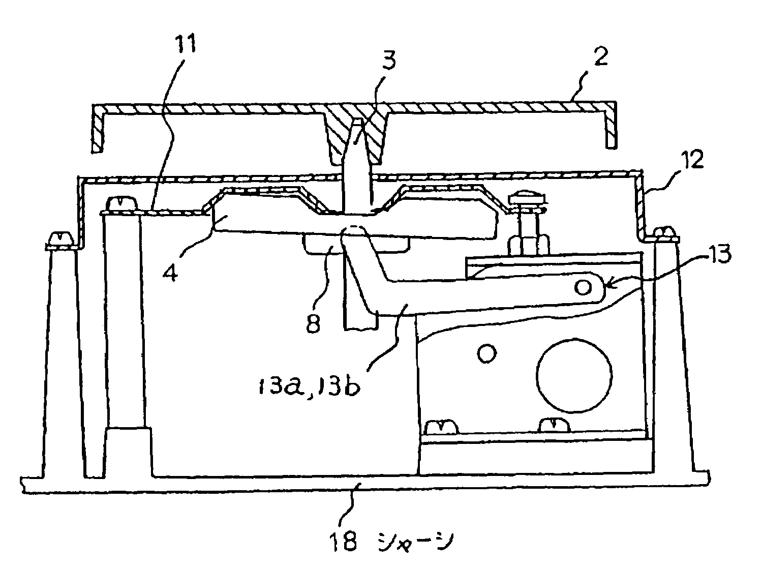
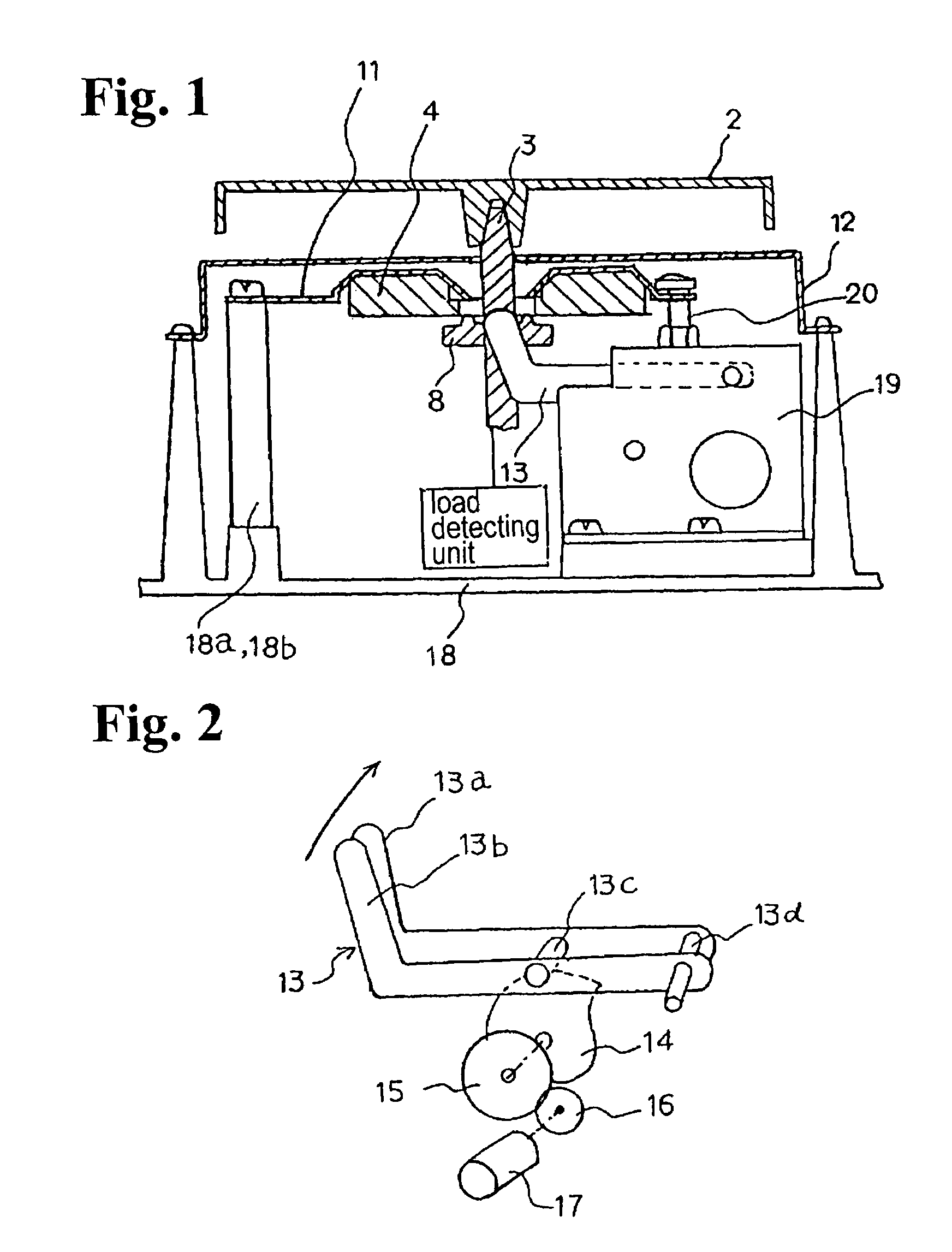
[0022]Hereunder, embodiments of the invention will be explained with reference to the accompanying drawings. FIG. 1 shows a structure of an essential part of an electronic balance according to an embodiment. The electronic balance is formed of a load transmitting mechanism for transmitting a load of a sample on the electronic balance to a load detecting unit; a sensitivity calibration mechanism for calibrating sensitivity with a calibration weight; and a weight holding mechanism for holding the calibration weight when the sensitivity calibration is not carried out. The load transmitting mechanical portion includes a sample plate 2 for placing a sample and a sensitive member 3 inserted into a concave portion formed in a backside of the sample plate 2 at a center portion thereof.

[0023]The sensitivity calibration mechanism includes a disk-shape calibration weight 4 provided with a through-hole for inserting the sensitive member 3 at a center portion thereof; and a weight moving mechani...


PUM


Abstract

An electronic balance includes a sample plate for placing a sample, a load detecting unit for determining a weight of the sample, a sensitivity calibration mechanism having a calibration weight disposed under the sample plate for applying a load of the calibration weight to the load detecting unit, a weight holding member with a spring property for holding the calibration weight when the load of the calibration weight is not applied to the load detecting unit, and a pressing member disposed above the weight holding member for restricting an upper movement of the weight holding member. The load detecting unit converts a load of the sample placed on the sample plate into an electrical signal according to a sensitivity coefficient to determine the weight of the sample. The sensitivity coefficient is calibrated when the load of the calibration weight is applied to the load detecting unit.

Description

BACKGROUND OF THE INVENTION AND RELATED ART STATEMENT[0001]The present invention relates to an electronic balance having a built-in calibration weight.[0002]In general, a conventional electronic balance includes a load detecting unit having a combination of an electromagnetic force balance mechanism and a load sensor in a housing. The load detecting unit detects a load applied to a sensitive member in proportion to a load of a sample placed on a sample plate.[0003]In the electronic balance having the load detecting unit as described above, there may be deviation (error) in a measured result (displayed value) according to a change in an environmental condition, such as a temperature and an air pressure, and lapse of time. Therefore, in order to accurately measure a weight of a sample all the time, it is required to carry out an automatic measurement sensitivity calibration (hereinafter, simply referred to as “sensitivity calibration”). Normally, a weight for the sensitivity calibrati...

Claims


Application Information

Patent Timeline
Patent Type & Authority Patents(United States)
IPC IPC(8): G01G19/52G01G23/02G01G23/01
CPCG01G23/012
Inventor IIDUKA, ATSUSHI
Owner SHIMADZU CORP
Why Eureka
Try Eureka