Precision adjustable light barrier

a light barrier and precision technology, applied in the field of light barriers, can solve the problems of insufficient evaluation of inability to completely eliminate the influence of neighboring systems, and inability to fully evaluate the information contained in the distribution of light in the beam cross-section, etc., and achieve the effect of reducing the alignment tim

Inactive Publication Date: 2007-02-13
SICK AG
View PDF17 Cites 4 Cited by
  • Summary
  • Abstract
  • Description
  • Claims
  • Application Information

AI Technical Summary

Benefits of technology

[0006]It is an objective of the present invention to provide a light barrier with an improved alignment device that reduces the alignment time and, most importantly, that ensures the precise alignment of the light receiver and the light emitter needed for its secure functioning.
[0008]A further embodiment of the invention employs adjustable holders that are secured to a movable tool of the press. This has the benefit that, during the working movement of a portion of the protected machine, for example a movable tool, the protection mechanism moves with the movable tool. This preserves the accurate orientation of the light barrier at the protection zone.
[0009]The advantage of the present light barrier is that it uses an economical alignment plate with a light entry opening and a target disk. By employing the reflection at an optical boundary area of the light receiver, the light receiver can be precisely aligned with the light emitter. In particular, if the beam cross-section at the light receiver is relatively large, a large target disk with a large capture range can be used and the benefits of this arrangement become very pronounced.
[0011]In an advantageous embodiment of the alignment plate, the light entry opening, the optical axis of the reception optics, and the target disk are arranged so that they lie on a common line. Thus, when the light entry opening is arranged in a marginal area of the reception optics, a maximum remaining area of the reception optics is available for the size of the target disk. The large target disk made possible in this way has the consequence that the visual field depicted on the target disk covers a large capture range. For this reason, the alignment aid can already be used for a rough alignment of the light receiver and the light emitter.
[0015]The light barrier with the alignment plate and internal reflecting surface of the present invention is especially advantageous when the receiver element has several individual photocells arranged in line or matrix form. For such light barriers, which are used not only to recognize the presence of an object in the path of a light beam, but also to furnish information at the same time as to the position of the object inside the cross-section of the light beam, a precise alignment of the light receiver on the light emitter is particularly important. The present invention for avoiding faulty alignments thus also assures an optimal function in terms of object recognition across the light beam cross-section.
[0017]In one embodiment of the invention, adjustable holders for the light emitter and receiver are attached to movable portions of the tool. This has the benefit that, during the working movement of a portion of the protected machine, for example a movable tool, the protection mechanism moves with the movable tool. This preserves the accurate orientation of the light barrier at the protection zone.

Problems solved by technology

Likewise, for light barriers with small sending and receiving angles, the influence from neighboring systems and the sensitivity to stray light are very limited or entirely prevented.
In such a case, a faulty alignment would have the result that the information contained in the distribution of light in the beam cross-section cannot be fully evaluated.
Drawbacks of these known methods for adjusting the light barrier are, for example, in the sighting telescope solution, the associated costs and the amount of space required, and in the solution using the reception signal, the time it takes to attain the desired orientation.

Method used


Image

  • Precision adjustable light barrier
  • Precision adjustable light barrier
  • Precision adjustable light barrier

Examples


Embodiment Construction

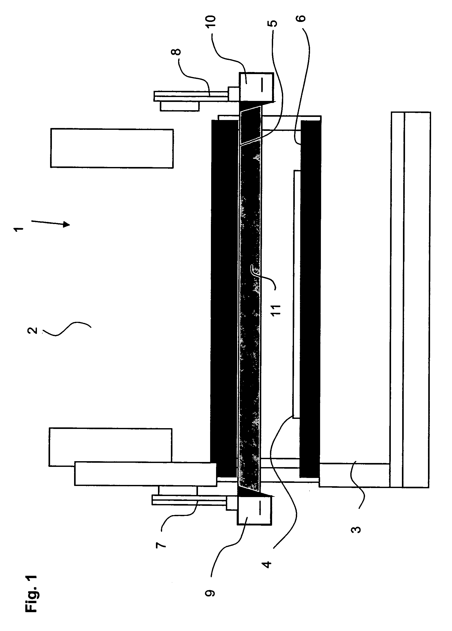
[0022]A bending press 1 shown in FIG. 1 has a movable tool 2 which moves vertically downward during a working cycle towards a stationary tool 3. Between the movable tool 2 and the stationary tool 3 is a workpiece 4 that is to be worked. The movable tool 2 and the stationary tool 3 have coordinated tool edges 5 and 6 for working workpiece 4. During a working cycle, the distance between the two tool edges 5 and 6 gradually diminishes. The working cycle of the bending press is under the control of a control unit (not shown). A triggering signal for this can be activated by a hand or foot switch, or with an automatic machine timer.

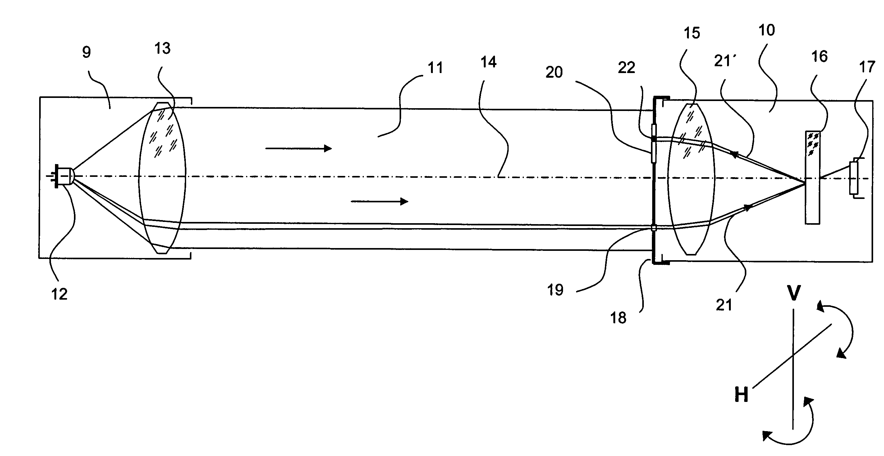
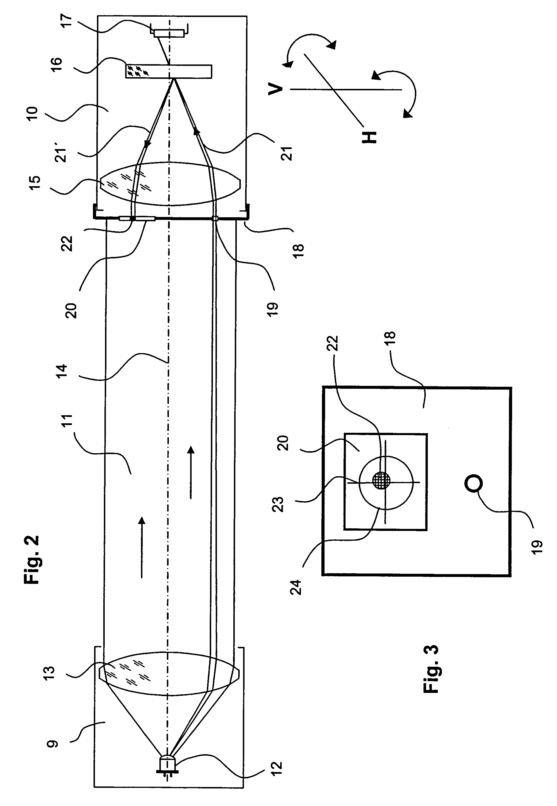
[0023]A light barrier having a light emitter 9 and a light receiver 10 is mounted on movable tool 2 with two adjustable holders 7 and 8. The installation of light emitter 9 and light receiver 10 is such that a bundle or array of rays 11 is formed between light emitter 9 and light receiver 10 directly in front of tool edge 5. If, during the vertical downward mo...


PUM

PropertyMeasurementUnit
receiving angleaaaaaaaaaa
surface areaaaaaaaaaaa
translucentaaaaaaaaaa

Abstract

A light barrier having a light emitter (9) spaced apart from a light receiver (10), the emitter including a light source (12) and transmission optics (13) emitting a substantially parallel light beam 11. The light receiver (10) and the light emitter (9) are aligned with each other for focusing the light beam (11) from the light emitter (9) by means of reception optics (15) on a reception element (17) for generating an electrical signal as a function of the light received. A partially reflecting optical boundary surface between the reception optics (15) and the reception element (17), and an alignment plate (18) which includes a light entry opening (19) and a target disk (20), are positioned in front of the reception optics (15) and are used for aligning the light receiver (10) and the light emitter (9).

Description

BACKGROUND OF THE INVENTION[0001]The invention concerns a light barrier with a light emitter spaced apart from a light receiver, the emitter including a light source and transmission optics and emitting a substantially parallel light beam. The light receiver and the light emitter are arranged to be aligned with each other for focusing the light beam from the light emitter by means of reception optics on a reception element for generating an electrical signal as a function of the light received.[0002]Such light barriers are used for the contactless detection of objects. In particular, when these light barriers are used to prevent accidents at machine tools, such as bending or edging presses, they must be exactly aligned during installation so that they function reliably. The necessary exact alignment is predicated upon the fact, among others, that the sending and receiving angle must be kept as small as possible (less than 2.5°), to prevent reflections and resulting failures to recog...

Claims


Application Information

Patent Timeline
Patent Type & Authority Patents(United States)
IPC IPC(8): H01J40/14F16P3/14G01V8/10G01V8/12
CPCF16P3/14F16P3/144G01V8/12G01V8/10B21D55/00
Inventor BERGBACH, ROLAND
Owner SICK AG
Why Eureka
Try Eureka