
Microwave sensor

a technology of micro-wave sensors and sensors, which is applied in the direction of burglar alarm mechanical vibration actuation, instruments, and reradiation, etc., can solve the problems of inability to ensure the credibility of microwave sensors, the difficulty of appropriately setting a level for distinguishing the detection target object from the plant, and the continuous generation of false alarms of microwave sensors, etc. problems, to achieve the effect of reducing false-alert generating factors, high object detection accuracy, and maintaining control stability

Inactive Publication Date: 2007-02-13
OPTEX CO LTD
View PDF5 Cites 6 Cited by
  • Summary
  • Abstract
  • Description
  • Claims
  • Application Information

AI Technical Summary

Benefits of technology

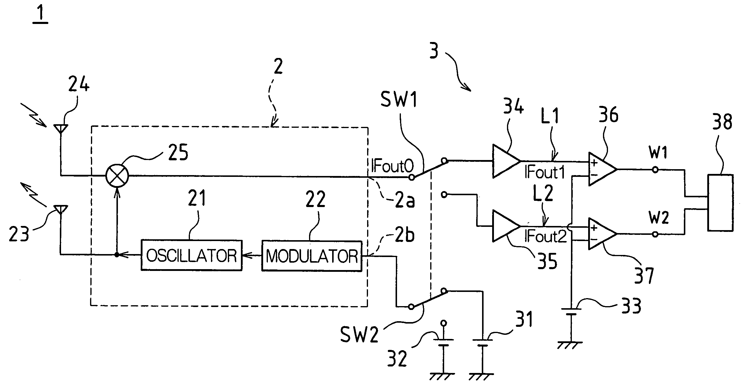
The present invention provides a microwave sensor that can stably maintain a credible object detection operation regardless of changes in environment. The sensor uses object decision means to measure the move distance of an object in a detection area and decide if it is a detection target object based on the measured move distance. The object decision means change the object decision move distance based on the number of times the object is decided to be the detection target object within a predetermined period of time. This prevents false alerts caused by wind or vibration and ensures that the sensor can detect objects accurately. The object decision move distance can be changed to a plurality of levels to achieve good convergence to the appropriate move distance and stability of the control.

Problems solved by technology

If this kind of sensor is used as a security sensor and if an object moving in the detection area is only decided as the detection target object by recognizing the temporal change in the phase difference, the following problems are posed.
These situations are caused not only by the swinging of plants but also by rainfall or vibration of the sensor itself (vibration due to the wind).
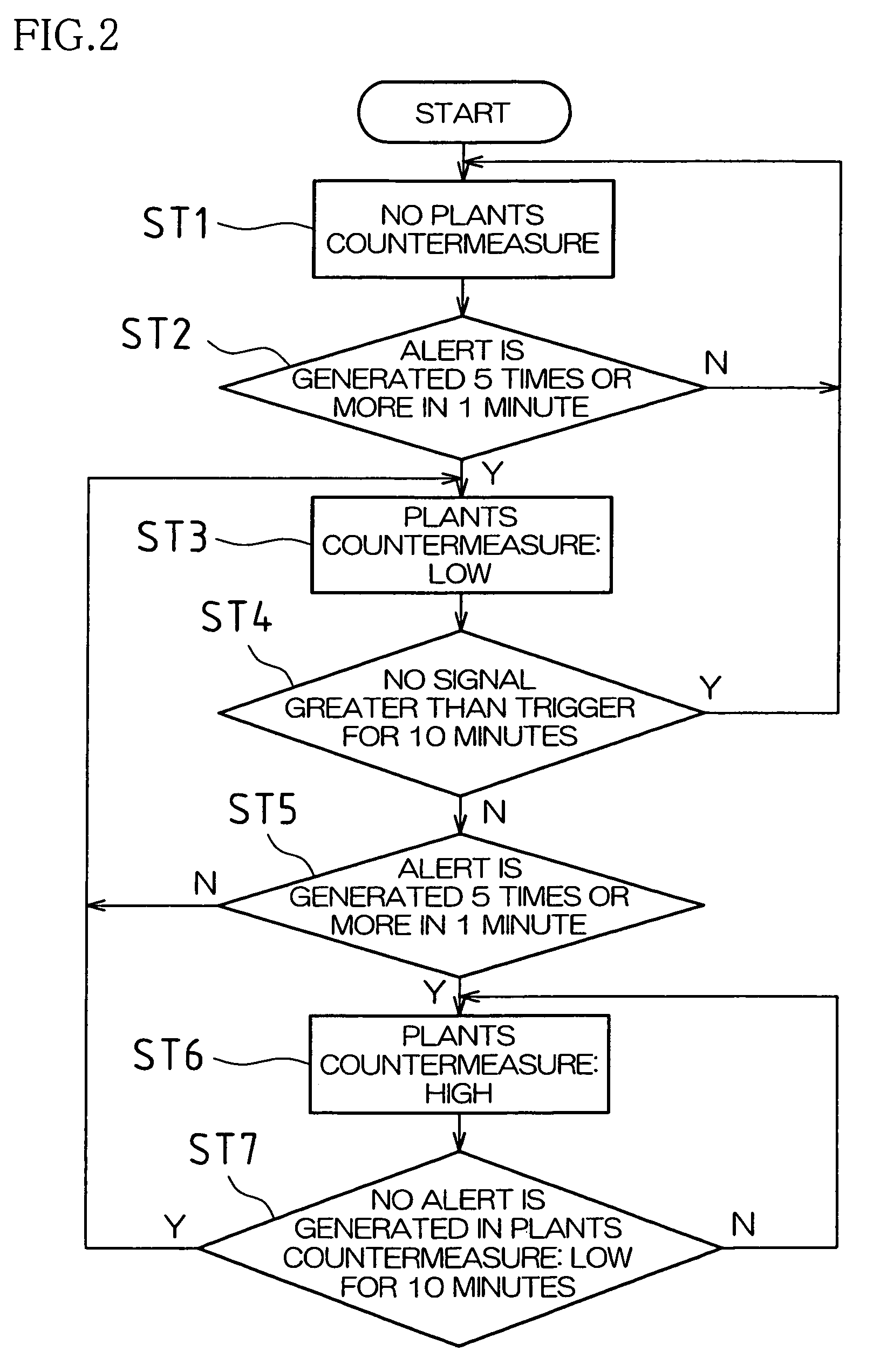
As stated above, although it is effective to distinguish the detection target object from plants or the like by recognizing the total move distance of the object in detection area (the plants countermeasure), it is difficult to appropriately set a level for distinguishing the detection target object from plants (a plants countermeasure level: a distance as a decision value for distinguishing the detection target object from plants or the like).
Especially, although this kind of microwave sensor is often used in combination with a passive infra-red (PIR) sensor which receives infrared radiation from a human body in the detection area and which detects an intruder from difference between the human body and an ambient temperature (as a combination sensor), if the plants countermeasure level is set low in this way, the microwave sensor may continuously generate false alerts.
Contrary, if the plants countermeasure level has been set high (an object is not detected unless the total move distance of the object becomes long (e.g., on the order of 100 cm), it is difficult to detect a moving human body passing transversely across the detection area (a moving object with less change in a relative distance to the microwave sensor) and, also in this case, credibility of the microwave sensor can not be ensured.

Method used


Image

  • Microwave sensor
  • Microwave sensor
  • Microwave sensor

Examples


Embodiment Construction

[0026]Embodiments of the present invention will now be described with reference to the drawings. This description will be made for the case that a microwave sensor is used for a security sensor and that the present invention is applied to a microwave sensor which decides a detection target object (such as an intruder) by utilizing two microwaves with different frequencies.

Description of Configuration of Microwave Sensor

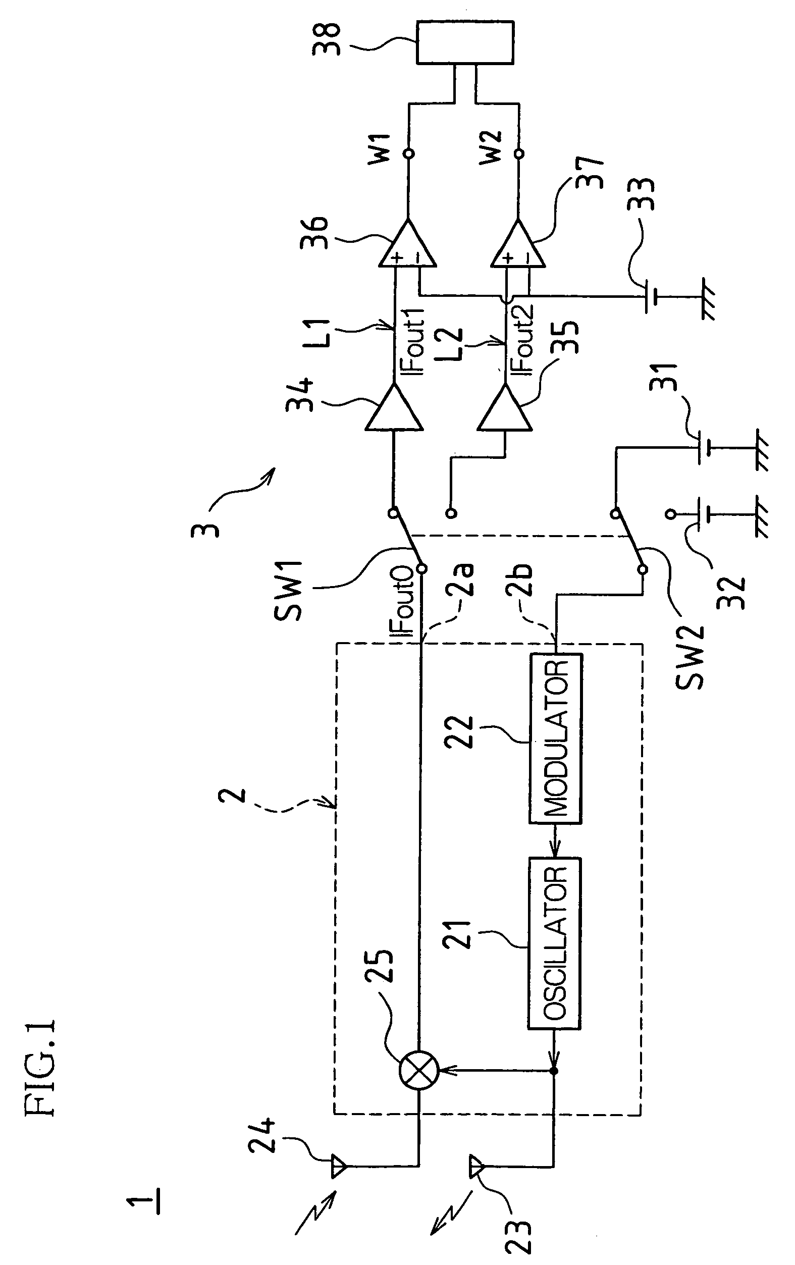
[0027]FIG. 1 is a schematic diagram of a circuit configuration of a microwave sensor 1 associated with one embodiment of the present invention. As shown in FIG. 1, the microwave sensor 1 is comprised of a radio frequency (RF) module 2 and a signal processing unit 3.

[0028]The RF module 2 is comprised of an oscillator 21 for oscillating a microwave, a modulator 22 for switching a frequency of the microwave oscillated by the oscillator 21, a transmitting antenna 23 for transmitting the microwave oscillated by the oscillator 21 toward a detection area, a receiving antenna...


PUM

PropertyMeasurementUnit
relative distanceaaaaaaaaaa
move distanceaaaaaaaaaa

Abstract

In one embodiment of a microwave sensor, when a “low” plants countermeasure is conducted, if an alert has been generated 5 times or more within 1 minute, an object decision move distance is changed to be longer and a “high” plants countermeasure is conducted. Subsequently, when assuming that the plants countermeasure is “low”, only if the alert is not generated within 10 minutes, the plants countermeasure is returned to “low”. Further, if the alert is not generated within 10 minutes in the status of the “low” plants countermeasure, the plants countermeasure is canceled.

Description

CROSS-REFERENCE TO RELATED APPLICATION[0001]This application claims priority under 35 U.S.C. §119 (a) to Patent Application No. 2004-028103 filed in Japan on Feb. 4, 2004, the content of which is hereby incorporated herein by reference in its entirety.BACKGROUND OF THE INVENTION[0002]1. Field of the Invention[0003]The present invention relates to a microwave sensor. More particularly, the present invention relates to a solution for improving accuracy of detection of an object to be detected by the microwave sensor.[0004]2. Description of the Related Art[0005]Conventionally, as a security apparatus, a microwave sensor is known for sending microwaves to a detection area and, if a human body (an intruder) exists in the detection area, the microwave sensor receives waves reflected from the human body (microwaves modulated by the Doppler effect) to detect the human body see, e.g., Japanese Patent Application Laid-Open Publication No. 2003-121532).[0006]Also, one type of microwave sensor ...

Claims


Application Information

Patent Timeline
Patent Type & Authority Patents(United States)
IPC IPC(8): G01S13/56G01S7/35G01N22/00G01S13/04G01S13/24G01S13/34G08B13/16G08B13/24
CPCG01S13/04G08B13/24G01S13/348G01S13/24G01S7/352G01S13/56G08B13/2491
Inventor TSUJI, MASATOSHI
Owner OPTEX CO LTD
Learn More