Projection-type display device and software program

a technology of projection-type display device and software program, which is applied in the direction of writing boards, television systems, instruments, etc., can solve the problems of complex operation, large volume of the whole system, and high cost of the whole system, and achieve the effect of easy rapid reading of the drawn image and less cos

Inactive Publication Date: 2007-02-13
RICOH KK
View PDF19 Cites 15 Cited by
  • Summary
  • Abstract
  • Description
  • Claims
  • Application Information

AI Technical Summary

Benefits of technology

[0011]The present invention is directed to the above-mentioned problems, and, an object of the present invention is to provide a projection-type display device in which, as a writing surface on which a user draws / writes an image is made approximately coincident with an image projection surface, operativity is improved, the whole system is simplified, and, also, the cost needed can be effectively reduced.
[0012]Further, according to the present invention, a software program for controlling the above-mentioned projection-type display device from an external personal computer etc., is provided. Thereby, it is possible to provide the projection-type display device less costly.
[0014]Thereby, as a user can draw any image such as letters / characters / pictures on the writing surface in a manner same as in a case of a common whiteboard or blackboard, and, thus, a user-friendly system can be provided. Further, as it is possible to draw an image on the writing surface superimposing manner with the projection image displayed on the projection surface, the drawn image and projection image are combined properly on the sight of the user. Accordingly, a high-operative system can be provided.
[0015]Further, as the drawn image is photographed through an image-pickup part having two-dimensionally disposed pixels (such as a so-called digital still camera), it is easy to read the drawn image rapidly, and, also, it is not necessary to prepare a large-sized configuration to read even a large-sized image drawn on a screen. Accordingly, the whole system can be effectively miniaturized, and, thus, it becomes less costly.

Problems solved by technology

Thus, the whole system becomes expensive and operation becomes complex.
Thus, the whole system may become bulky.
Also, as the screen is scanned by the scanner mechanically, a considerable time is required to read the whole image present on the screen.
However, in this art, as the scanner mechanically scans the image present on the screen, the problems same as in the above-mentioned art may occur, i.e., the whole system may become bulky.
However, no specific configuration of how to read a drawn image is disclosed in the publication.

Method used


Image

  • Projection-type display device and software program
  • Projection-type display device and software program
  • Projection-type display device and software program

Examples


first embodiment

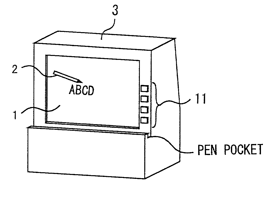
[0048]FIG. 1 shows an appearance of a projection-type display device in the present invention.

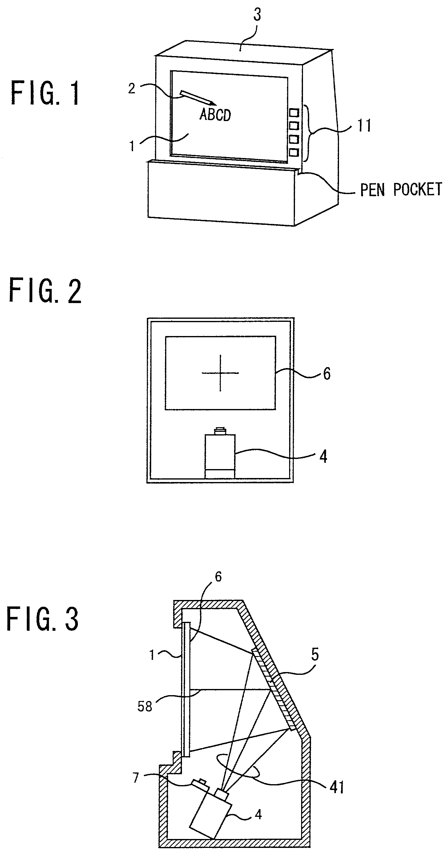
[0049]In this projection-type display device, a user can write, by using a pen 2 for writing, letters / characters, images, etc. on a writing field 1. As for the pen 2 for writing, a generally sold marker used for writing onto a whiteboard, such as a common pen employing alcoholic ink, may be used. Further, the writing field (sheet) 1 is made of material such that an image projected on a transparent screen 6 (see FIG. 2) provided on the side opposite to the user side can be sufficiently transmitted thereby. Thereby, the user can view an image projected on the transparent screen 6 by a projector 4 (see FIG. 2) through the writing field 1. In addition, such a treatment is made on a surface of the writing field 1 on which writing is made by the user that an image drawn thereon by ink may be easily erased by a cloth or the like, as in a common whiteboard.

[0050]The projection-type display device i...

second embodiment

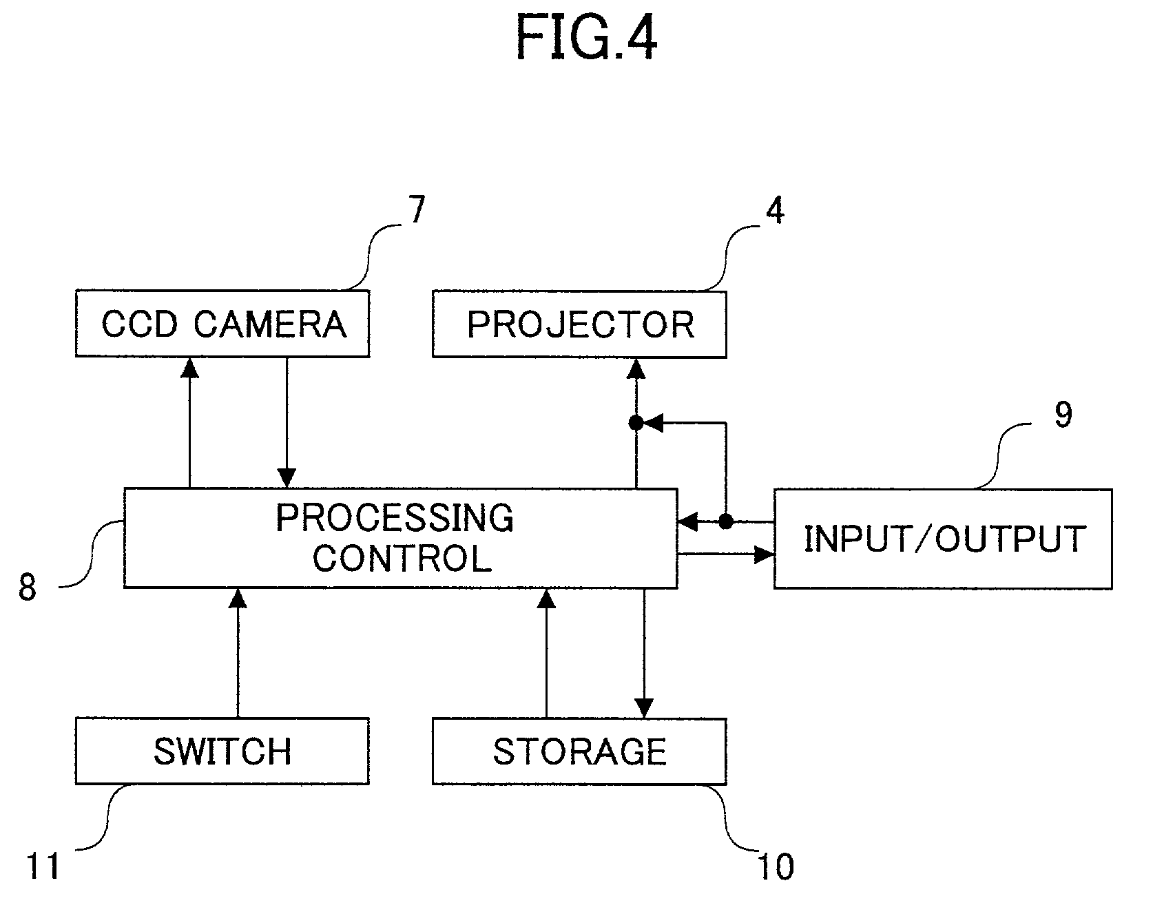
[0079] as shown in FIG. 9, the projector 4, CCD camera 7 and switches 11 are connected to a personal computer 108 provided inside or outside of a projection-type display device as shown in FIG. 9. USB, IEEE1394, SCSI, etc. are applied as the interface for connecting these respective components. Driver software (a CCD camera driver 1081, a projector driver 1082, and a switch driver 1083) for controlling the CCD camera 7, projector 4, and switches 11 is installed in the personal computer 108, and, thereby, control of each component, and input and output of various instructions and / or data therefrom / thereto are performed.

[0080]Thus, according to the second embodiment, the configuration of the projection-type display device is simplified, and, also, a predetermined software provides various control processing needed. Thereby, the projection-type display device can be provided at low cost.

[0081]Since the other configurations and operations are the same as those of the first embodiment, d...

third embodiment

[0085]In the configuration of the third embodiment, the light-blocking plate 21 is removed and thus, the transparent screen 6 can have an image projected thereunto from the projector 4 at a time of image projection, as shown in FIG. 10A. On the other hand, at a time of photography of a user-drawn image formed on the writing field 1, the light-blocking plate 21 is placed in front of the projector 4, and thereby, the light beam emitted by the projector 7 is prevented from reaching the transparent screen 6, as shown in FIG. 10B. Removing and inserting of the light-blocking plate 21 mentioned above is performed by using a stepper motor 22, or the like which is driven and controlled by the processing control part 8.

[0086]FIG. 11 is a block diagram showing a configuration of the projection-type display device in the third embodiment. Thus, different from the above-mentioned first embodiment, the projection-type display device according to the third embodiment includes the stepper motor 22...


PUM


Abstract

A projection surface on which a predetermined projection image is projected is provided; a writing surface on which an image can be drawn directly in a superimposing manner with a projection image displayed on the projection surface is provided; and a photography part photographing an image drawn on the writing surface by means of an image-pickup part comprising two-dimensionally-disposed pixels is provided.

Description

BACKGROUND OF THE INVENTION[0001]1. Field of the Invention[0002]The present invention relates to a projection-type display device, and, in particular, to a projection-type display device having a novel feature of improving a system of combining an image projected and an image drawn thereon by a user.[0003]2. Description of the Related Art[0004]Conventionally, generally, a projection-type display device is applied to a projector, a media board with a display device, a personal computer, etc., is used as a monitor for two or more persons in a meeting, a lecture, etc., or is used as a monitor, such as in a personal computer used individually.[0005]Such a projection-type display device is demanded to have a feature such that letters / characters, and / or pictures may be drawn on a display device in a superimposing manner together with an image projected there, and, also, the thus-drawn letters / characters and / or pictures can be obtained as electronic data.[0006]For this purpose, an art is p...

Claims


Application Information

Patent Timeline
Patent Type & Authority Patents(United States)
IPC IPC(8): G09G5/00B43L1/04B43L1/10G03B21/10G03B21/26G06F1/16G06F3/033G06F3/042H04N1/00H04N1/195H04N5/74
CPCG06F1/1601G06F3/033G06F3/0425H04N1/00283H04N2201/0438H04N1/195H04N9/3141H04N2201/001
Inventor KITAGUCHI, TAKASHIKITAZAWA, TOMOFUMISASAKI, SABURO
Owner RICOH KK
Why Eureka
Try Eureka