
Determination of thin film topography

a thin film topography and topography technology, applied in the direction of measuring devices, instruments, using optical means, etc., can solve the problem that current thin film measurement methods do not possess such a universal appeal, and achieve the effect of improving accuracy

Inactive Publication Date: 2007-02-13
TECHNION RES & DEV FOUND LTD
View PDF13 Cites 68 Cited by
  • Summary
  • Abstract
  • Description
  • Claims
  • Application Information

AI Technical Summary

Problems solved by technology

Current thin film measurement methods do not possess such a universal appeal.

Method used


Image

  • Determination of thin film topography
  • Determination of thin film topography
  • Determination of thin film topography

Examples


Embodiment Construction

[0052]Interferometric techniques play an important role in the measurement of thin transparent films on substrates. The simplest interferometric method of measuring the thickness hfilm,(x,y) of a non-uniform thin film involves creating an image by superposition of beams reflected from two interfaces: air / film and film / substrate.

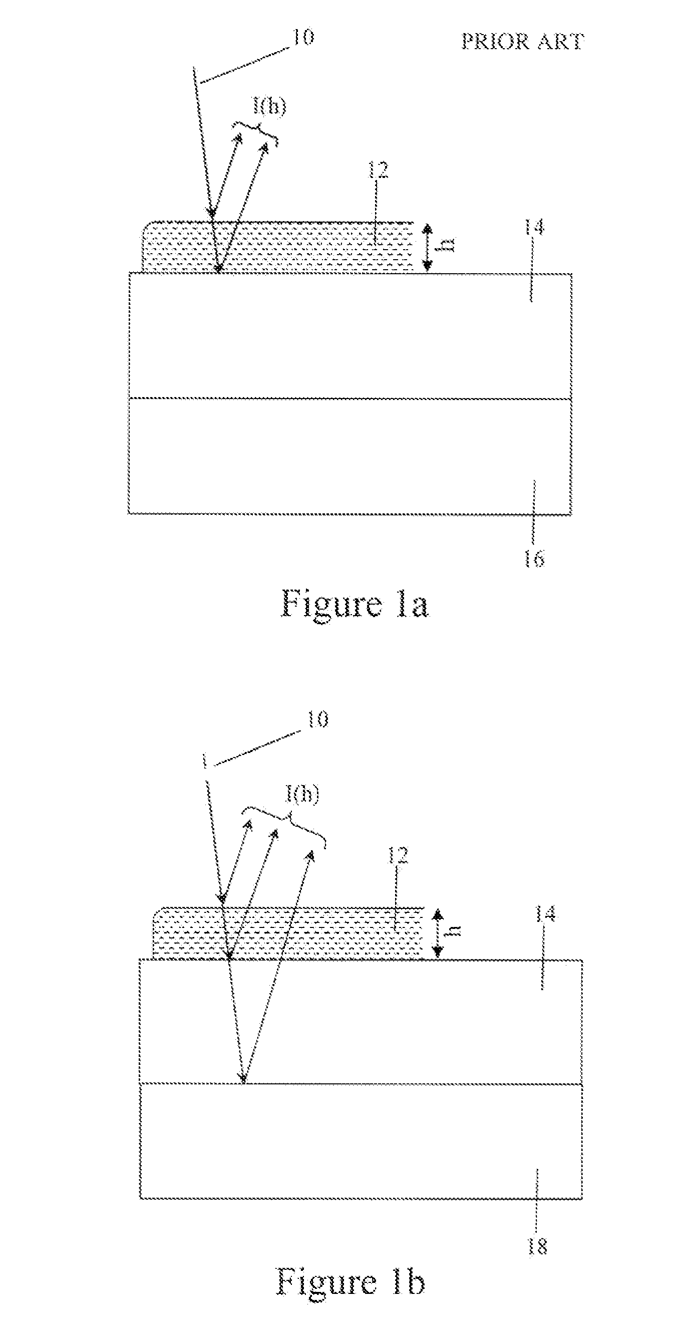
[0053]FIG. 1a illustrates two-beam interferometry for measuring the thickness of a thin water film 12 over a mica substrate 14. Incident light beam 10, which is either coherent or partially coherent with coherence length that is at least equal to the maximum thickness of the film (hereinafter—partially coherent), is directed onto thin film 12, and is partially reflected and partially refracted through. The refracted portion of the beam traverses through the thin film and then reflected by the water-mica interface. Absorbing grease 16 laid beneath mica substrate 14 is provided to inhibit reflections off the back surface of the mica substrate 14.

[0054]This meth...


PUM


Abstract

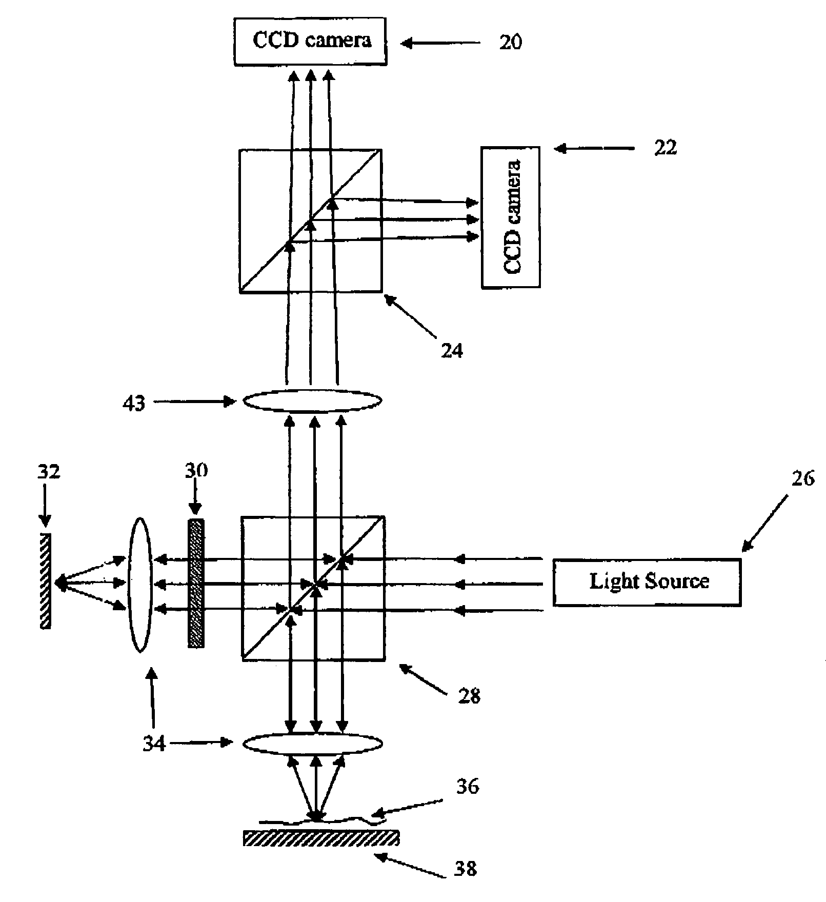
A method and device for determining the topography of a thin film having a front surface and a back surface. The method comprises: irradiating the film with an incident coherent or partially coherent light beam so as to get two reflected beams, the first reflected beam being reflected from the front surface of the film, and the second beam being reflected from the back surface of the film; creating an interferometric image from a united beam comprising the two reflected beams and a reference beam, the reference beam originating from the incident beam, and made to be substantially parallel to the two reflected beams. The reference beam acquires a phase shift. The interferometric image is created the interference between a combined beam comprising the reference beam and the second reflected beam, and the first reflected beam, thus acquiring information on the topography of the film, that cannot be acquired using the two reflected beams alone.

Description

FIELD OF THE INVENTION[0001]The present invention relates to determining the topography of thin films.BACKGROUND OF THE INVENTION[0002]The non-destructive nature of optical methods makes them very important tools in investigating thin films. Several interferometric and ellipsometric tools are widely used for thin film thickness measurement in industry and basic science (on ellipsometry see, for example: M. Steinberg et al, A New Method for Measurement on Surfaces and[0003]Surface Layers, Mater. Sci. and Eng., 1980, 42, 65–69. D. Beaglehole, H. K. Christenson, “Vapour adsorption on mica and silicon-entropy effects, layering and surface forces”, J.Phys.Chem., 96, 3395–3403, (1992). D. Beaglehole, “Performance of a microscopic imaging ellipsometer”, Rev.Sci.Instrum., 59, 2557, (1998)). The typical thickness of films in microelectronics varies in the range of 0÷10 μm. The development of faster microelectronic devices demands development of very thin film technology and therefore new cha...

Claims


Application Information

Patent Timeline
Patent Type & Authority Patents(United States)
IPC IPC(8): G01B11/02G01B9/02G01B11/06
CPCG01B11/0675G01B9/02
Inventor LEIZERSON, ILYALIPSON, STEPHEN G.
Owner TECHNION RES & DEV FOUND LTD
Learn More