Fingerprint input apparatus

a technology of input apparatus and fingerprint, which is applied in the direction of subcutaneous biometric features, instruments, person identification, etc., can solve the problems of large thickness and size of the apparatus, inability to manufacture the apparatus at low cost, and the resultant image tends to distor

Inactive Publication Date: 2007-02-13
NEC CORP
View PDF25 Cites 15 Cited by
  • Summary
  • Abstract
  • Description
  • Claims
  • Application Information

AI Technical Summary

Benefits of technology

[0006]It is an object of the present invention to provide a relatively low-profile, compact, inexpensive fingerprint image input apparatus.
[0007]It is another object of the present invention to provide a fingerprint image input apparatus capable of obtaining an image free from distortion.

Problems solved by technology

In these conventional fingerprint input apparatuses, when the optical components such as a lens and prism or a fiber are used, a space for the sizes of these optical components and their mounting positions is required to result in a large thickness and size of the apparatus.
In addition, since these optical components are relatively expensive, the apparatus cannot be manufactured at low cost.
When the fingerprint image is optically processed using these optical components, the resultant image tends to distort.
The scheme of directly inputting a fingerprint image using the electrostatic capacitance is susceptible to external static electricity and difficult to obtain a high sensitivity.

Method used


Image

  • Fingerprint input apparatus
  • Fingerprint input apparatus
  • Fingerprint input apparatus

Examples


first embodiment

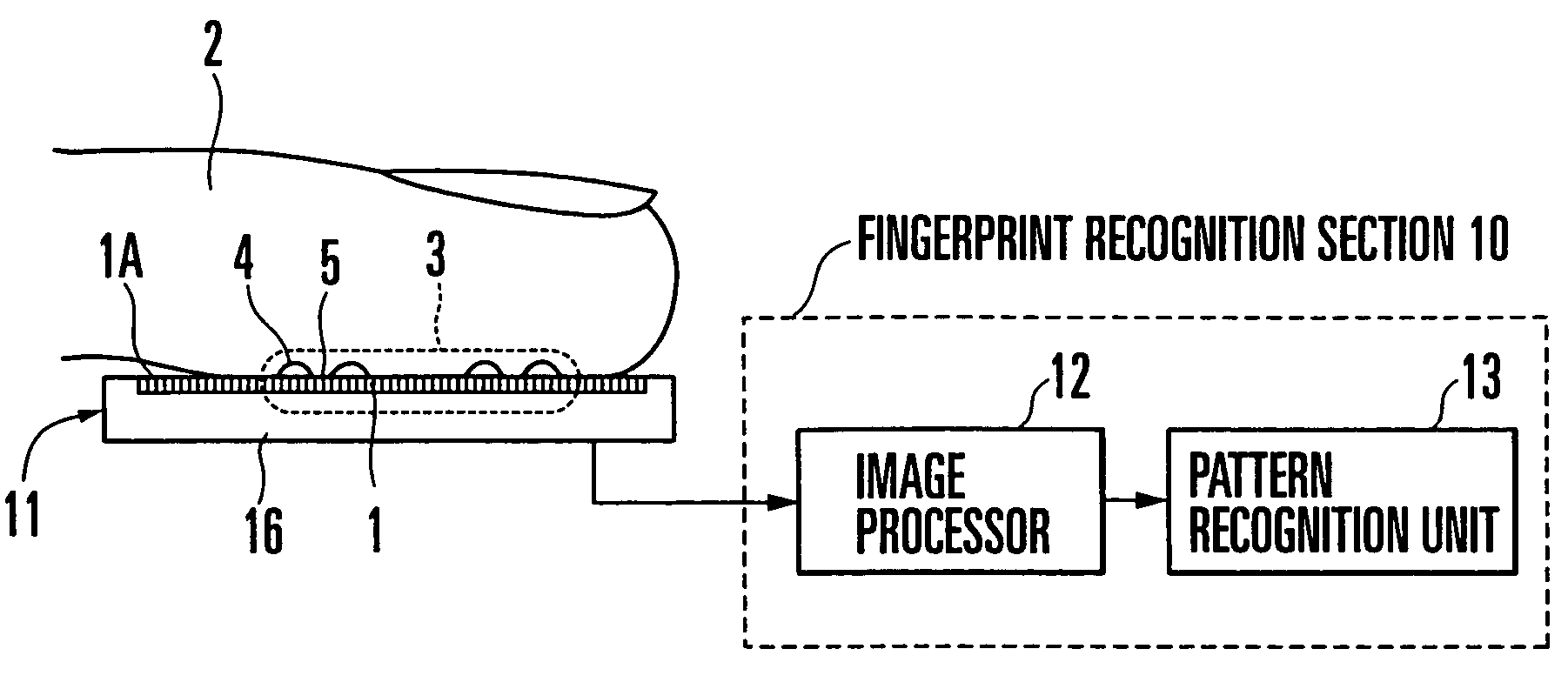
[0015]FIG. 1 shows a fingerprint input apparatus according to the present invention. Referring to FIG. 1, reference numeral 11 denotes a two-dimensional image sensor (to be referred to as an image sensor hereinafter) for two-dimensionally detecting the light intensity in accordance with the three-dimensional pattern of a skin surface 3 of a finger 2; 12, an image processor for image-processing an output from the image sensor 11 to generate a fingerprint pattern; and 13, a pattern recognition unit for extracting the features of the fingerprint pattern generated by the image processor 12 and recognizing the pattern by comparing the extracted features with a predetermined reference pattern.

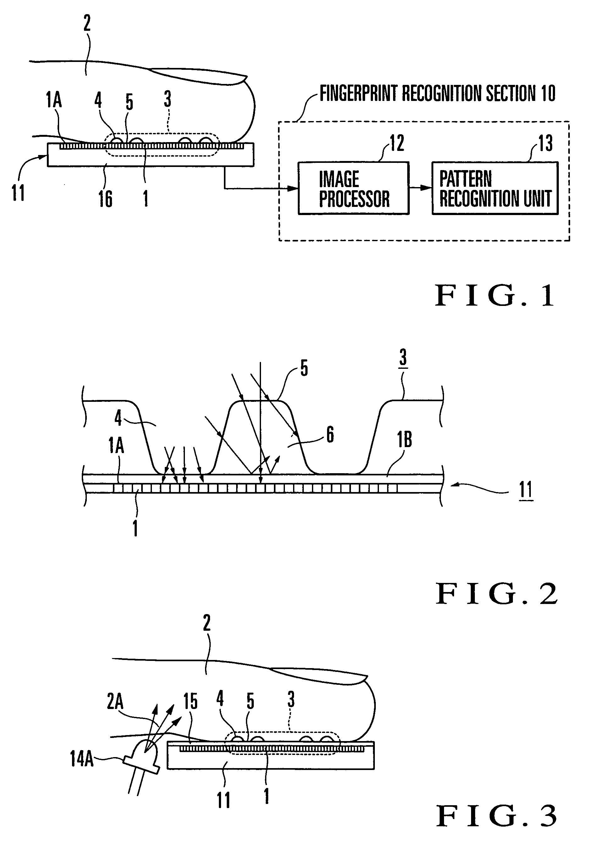
[0016]The image sensor 11 comprises a substrate 16 and a large number of light-receiving elements 1 two-dimensionally arranged in a matrix on the substrate 16. A two-dimensional image is formed on the basis of an output from each light-receiving element 1. As shown in FIG. 2, a transparent cover 1B c...

second embodiment

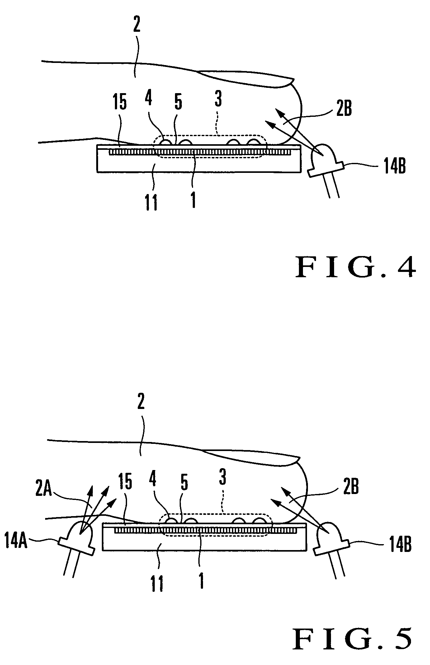
[0024]FIG. 3 shows the schematic arrangement of a fingerprint input apparatus according to the present invention.

[0025]In the first embodiment, the scattered light from the inside of the finger 2 is generated by the ambient light of the finger 2. For this reason, any special light source need not be provided. However, when a fingerprint input apparatus is used in a place where no ambient light is available, a light source such as an LED (Light-Emitting Diode) is arranged to irradiate the finger 2.

[0026]Referring to FIG. 3, reference numeral 14A denotes a light source arranged on the same surface side as that of an image sensor 11 so as to oppose a finger pad portion 2A of a finger 2. The finger pad portion 2A is irradiated upward with light from the light source 14A to generate scattered light inside the finger 2. As compared with the case in which the light source is disposed above the finger 2 to irradiate it, the light source does not interfere with operation of placing the finge...

third embodiment

[0029]FIG. 4 shows the schematic arrangement of a fingerprint input apparatus according to the present invention.

[0030]Referring to FIG. 4, reference numeral 14B denotes a light source arranged on the same surface side as that of an image sensor 11 so as to oppose a fingertip portion 2B of a finger 2. The fingertip portion 2B is irradiated obliquely upward with light from the light source 14B to generate scattered light inside the finger 2.

[0031]According to this embodiment, since the fingertip portion 2B has an almost hemispherical surface curved downward in the forward direction, scattered light can be uniformly generated inside the finger 2 upon irradiating the finger 2 with the light from the light source 14B.


PUM


Abstract

A fingerprint input apparatus includes scattered light and a two-dimensional image sensor. The scattered light is generated inside a finger having a fingerprint pattern in accordance with external light. The fingerprint pattern is made up of a ridge portion and a valley portion. The two-dimensional image sensor is made of a large number of light-receiving elements arranged in a two-dimensional array. The image of the fingerprint pattern is input to a light-receiving surface of the light-receiving element. The light-receiving element whose light-receiving surface is in substantially contact with the ridge portion detects as the ridge portion a bright portion where the scattered light emerging from the finger reaches at a high intensity. The light-receiving element whose light-receiving surface corresponds to the valley portion via a space detects as the valley portion a dark portion where the scattering light emerging from the finger reaches at a low intensity.

Description

CROSS REFERENCE TO RELATED APPLICATION[0001]This application is a continuation of application Ser. No. 09 / 494,506 filed Jan. 31, 2000 now U.S. Pat. No. 6,829,375, the benefit of the filing date of which is hereby claimed.BACKGROUND OF THE INVENTION[0002]The present invention relates to a fingerprint input apparatus and, more particularly, to a fingerprint input apparatus capable of directly reading a fingerprint image using a two-dimensional image sensor.[0003]In a conventional fingerprint input apparatus of this type, the skin surface of the fingertip is irradiated with light at a predetermined angle using optical components such as a lens and prism or a fiber. The light reflected by the skin surface is focused to output a fingerprint image. Alternatively, a study has been made on a scheme of directly inputting a fingerprint image using an electrostatic capacitance instead of obtaining a fingerprint image using the optical system.[0004]In these conventional fingerprint input appara...

Claims


Application Information

Patent Timeline
Patent Type & Authority Patents(United States)
IPC IPC(8): G06K9/00A61B5/117G06T1/00G06T7/00
CPCG06K9/0004G06K9/00067G06K2009/00932G06K2009/0006G06V40/1341G06V40/1347G06V40/1318G06V40/14
Inventor HIGUCHI, TERUYUKI
Owner NEC CORP
Why Eureka
Try Eureka