Controlling transmission mode on basis of power in preceding time slot

a transmission mode and power supply technology, applied in the field of transmitters and methods of operation, can solve the problems of reducing the accuracy of measurement results, and requiring the provision of extra components, and achieve the effect of less expensiv

Inactive Publication Date: 2007-02-13
NOKIA CORP
View PDF9 Cites 47 Cited by
  • Summary
  • Abstract
  • Description
  • Claims
  • Application Information

AI Technical Summary

Benefits of technology

[0020]This can allow the effects of a power detector which is temperature sensitive to be ameliorated.
[0023]This sample and hold circuit is a particularly effective way to prevent output power changing over a time slot. Using the sample and hold circuit in the linear mode and operating the power amplifier in the linear mode when the non-linear mode would normally be used, but because the transmission power in the time slot and in the immediately preceding time slot would otherwise result in the power varying over the time slot, has two consequences. Firstly, it prevents the power varying over that time slot. Also though, since amplifiers operating in linear modes conventionally are less efficient, a result is that the power amplification is less efficient, so more power is used for the same output power. The applicant considers that this is an acceptable disadvantage in light of the positive effects of this, namely obtaining a non-varying output power over the time slot.

Problems solved by technology

Heat from the components is transferred to the power detector 14 and may result in a decrease in the accuracy of its measurements.
The resulting measurement error may be of the order of 2 mV per degree centigrade, which may result in measurement results that are erroneously low.
This is undesirable.
However, this requires the provision of extra components.
Furthermore, the provision of temperature compensation means that are capable of responding to very rapid temperature changes is not straightforward.
However, this requires the provision of external components and may increase the size of the amplifier arrangement 2.

Method used


Image

  • Controlling transmission mode on basis of power in preceding time slot
  • Controlling transmission mode on basis of power in preceding time slot
  • Controlling transmission mode on basis of power in preceding time slot

Examples


Embodiment Construction

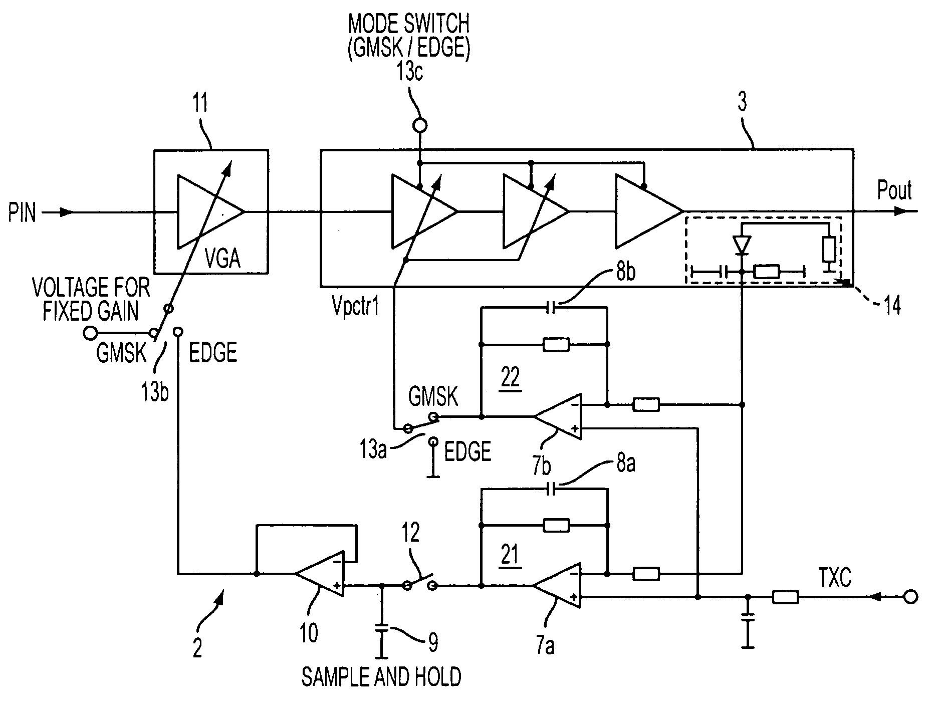
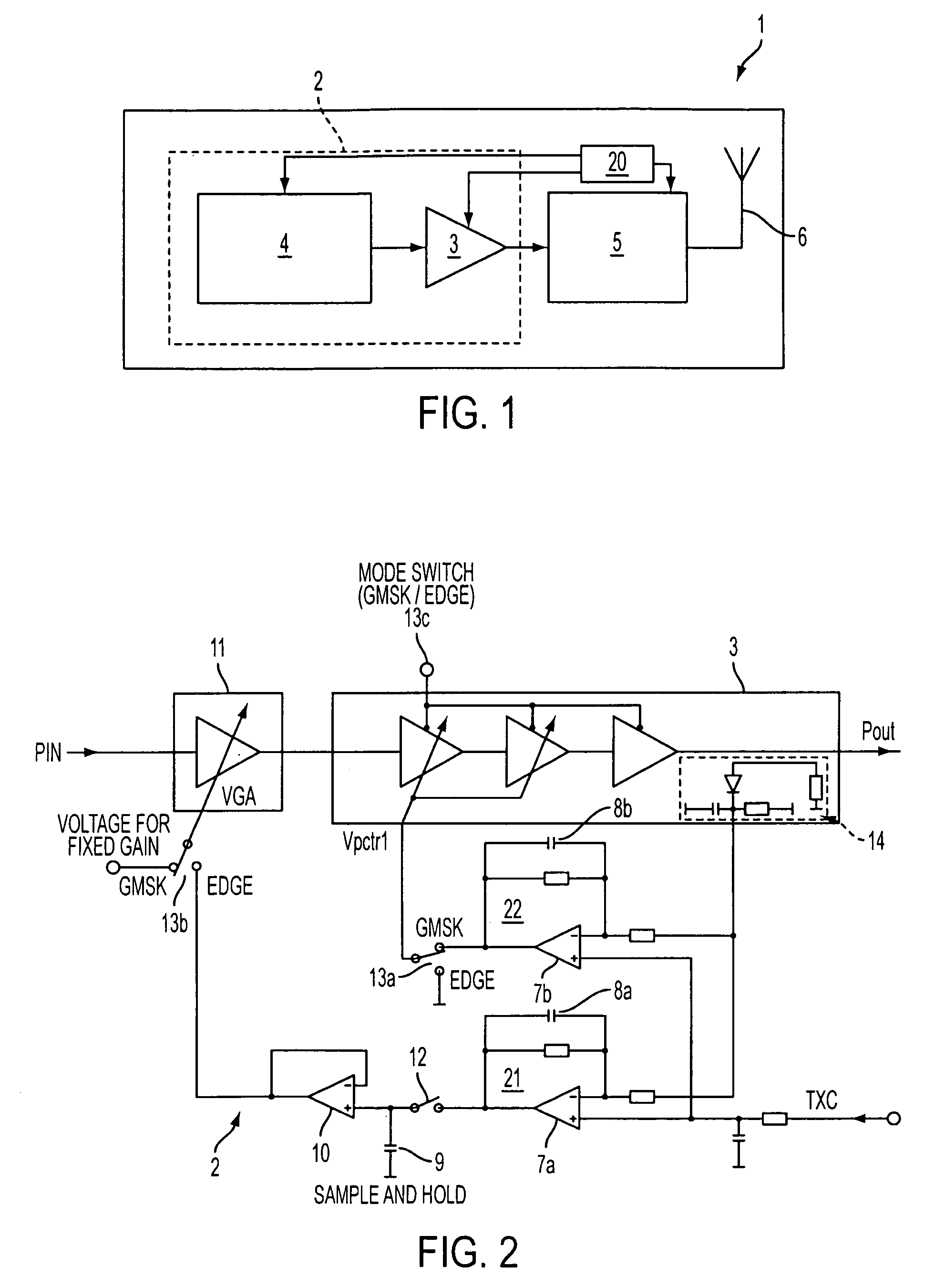
[0036]In an embodiment of the invention, a transmitter 2 comprises a power amplifier 3 and power controller 4, as shown in FIGS. 1 and 2. The power amplifier 3 is capable of both linear and non-linear operation, and is controlled by a controller 20 and first and second control loops 21, 22 as described above in relation to the prior art.

[0037]However, instead of using the first control loop 21 exclusively for time slots in which data signals with a high degree of amplitude modulation are to be transmitted, the first control loop 21 is also used when non-amplitude modulated signals are transmitted if the output power to be produced by the power amplifier 3 is low and in the immediately preceding time slot a high output power was produced.

[0038]For example, the communications device 1 may be a mobile transmitter arranged to transmit data using EDGE and GMSK modulation schemes. It may alternatively be a mobile, or cellular, telephone, or any other transmitter device. The power controll...


PUM


Abstract

A transmitter 2 comprises a power amplifier 3 and power controller 4. The power amplifier 3 is capable of both linear and non-linear operation, and is controlled by a controller 20 and first and second control loops 21,22. The second control loop 22 is used with the transmission of GMSK modulated signals, which have no amplitude modulation, operating the power amplifier 3 in a non-linear mode. The first control loop 21 is used for the transmission of EDGE modulated signals, which have a substantial amount of amplitude modulation, operating the power amplifier 3 in a linear mode. The first control loop 21 is also used with GMSK time slots if the output power to be produced by the power amplifier 3 is low and the power of an immediately preceding time slot is high. In this case, a sample and hold circuit 9, 10 of the first control loop 21 is used when the power detector voltage in the power amplifier would change over the time slot by cooling, avoiding the possibility of the power level varying over the time slot.

Description

[0001]This application claims priority to GB 0412188.5 Filed Jun. 1, 2004.FIELD OF THE INVENTION[0002]The invention relates to a transmitter, and a method of operating a transmitter. It particularly relates to a transmitter in which data is modulated using one of a first modulation scheme and a second modulation scheme in each of a series of time slots, and to a method comprising transmitting data in a series of time slots, and applying one of a first modulation scheme and a second modulation scheme to data in each time slot.BACKGROUND OF THE INVENTION[0003]FIG. 1 depicts a communication device 1 arranged to transmit data in a series of time slots, such as is used in TDMA systems. The communication device 1 comprises a transmitter 2 that includes a power amplifier 3 and a power controller 4 arranged to control the power amplifier 3, together with a RX-TX switch 5 and an antenna 6. The power amplifier 3 supplies power to the antenna 7. A controller 20 is operable to control all the o...

Claims


Application Information

Patent Timeline
Patent Type & Authority Patents(United States)
IPC IPC(8): H04B1/02H01Q11/12H03F1/02H03F1/06H03F3/24H04B1/04
CPCH03F1/0205H03F1/0211H03F1/0244H03F3/24H04B1/04H03F1/0277H04B2001/045H03F2200/451H03F1/02
Inventor WEISS, MANFRED
Owner NOKIA CORP
Why Eureka
Try Eureka