System for influencing the speed of a motor vehicle

a technology for influencing the a system, which is applied in the direction of process and machine control, using reradiation, instruments, etc., can solve the problem of not monitoring the driving speed of a motor vehicle traveling ahead, and achieve the effect of avoiding false evaluation and increasing safety during identification

Active Publication Date: 2007-02-13
LUCAS AUTOMOTIVE GMBH
View PDF92 Cites 47 Cited by
  • Summary
  • Abstract
  • Description
  • Claims
  • Application Information

AI Technical Summary

Benefits of technology

[0019]In particular, to reduce the possible targets located in the lane in front of one's own vehicle, generally not the entire detection area—limited by the aperture of the (radar) sensor—is evaluated, but a reduced region in respect thereof. This measure reduces the number of objects to be observed. For simplicity's sake, however—insofar as there is no explicit reference thereto—it will be assumed below that the range actually evaluated and the detection area in front of one's own motor vehicle coincide.
[0091]To further increase selection safety of the target motor vehicle, determination can also be made as to whether an object located in the detection area in front of one's own motor vehicle goes below a predetermined distance and not in the lane of one's own motor vehicle is excluded from selection as a priority object. This strategy according to the invention allows for the circumstance that for targets a small distance away from one's own motor vehicle locating can no longer be done with the required accuracy. As objects of this kind are still detected via the so-called ancillary lobe of the radar sensor, it appears as if someone is cutting in to the lane of one's own motor vehicle from a neighboring lane.

Problems solved by technology

However, no monitoring of the driving speed of a motor vehicle traveling ahead takes place in this case.

Method used


Image

  • System for influencing the speed of a motor vehicle
  • System for influencing the speed of a motor vehicle
  • System for influencing the speed of a motor vehicle

Examples


Embodiment Construction

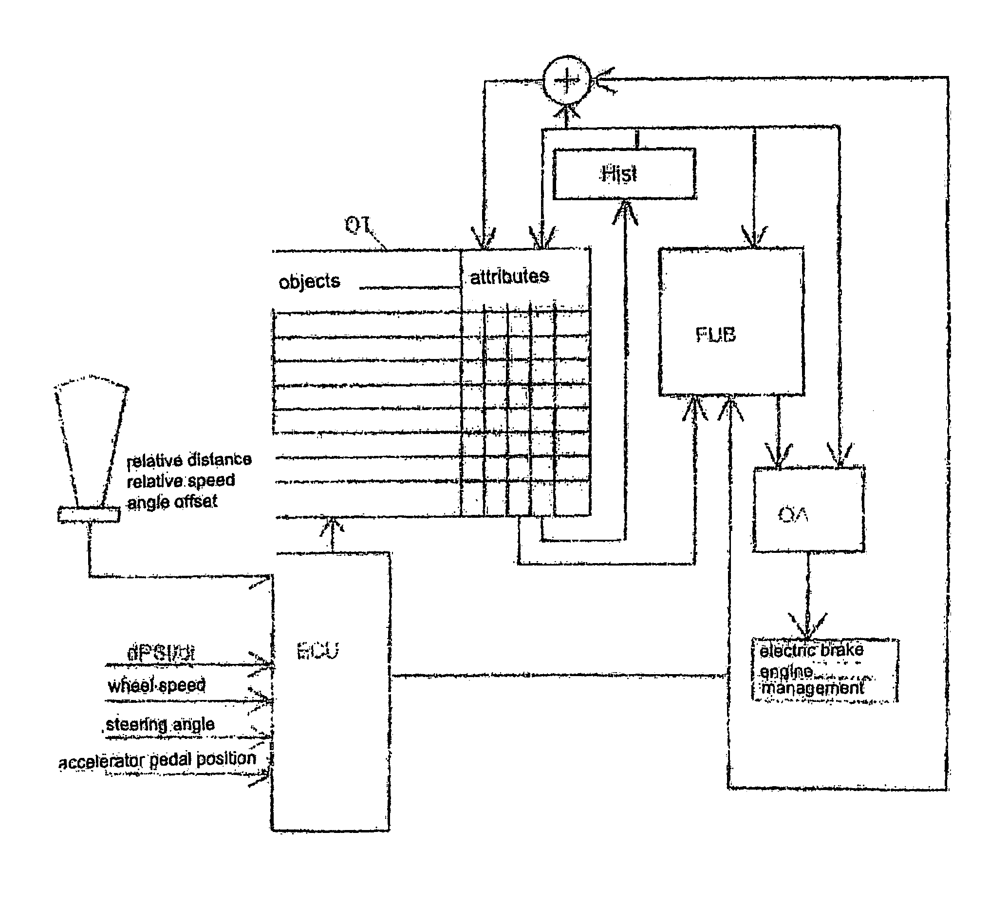
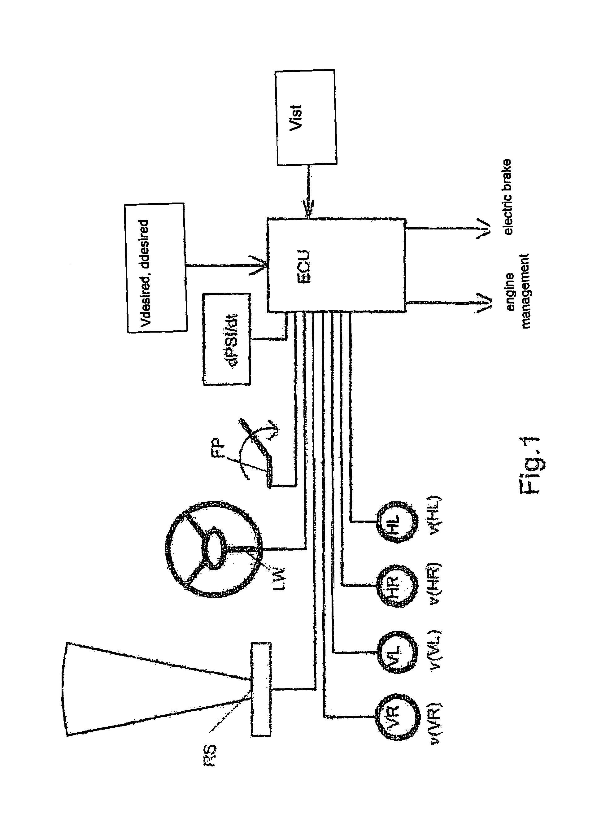
[0105]FIG. 1 shows an embodiment of a schematic block diagram of a system according to the invention for evaluating the driving environment of a motor vehicle and for influencing the speed of the motor vehicle. This system has an electronic control unit ECU, connected to a signal transmitter, which generates a signal characteristic of the desired speed Vdesired of the motor vehicle. The electronic control unit ECU further receives from a signal transmitter operating as a yaw rate sensor a signal characteristic of the rate of revolutions dPSI / dt of the motor vehicle about its vertical axis. Moreover, the electronic control unit ECU is connected to a signal transmitter operating as a radar sensor RS.

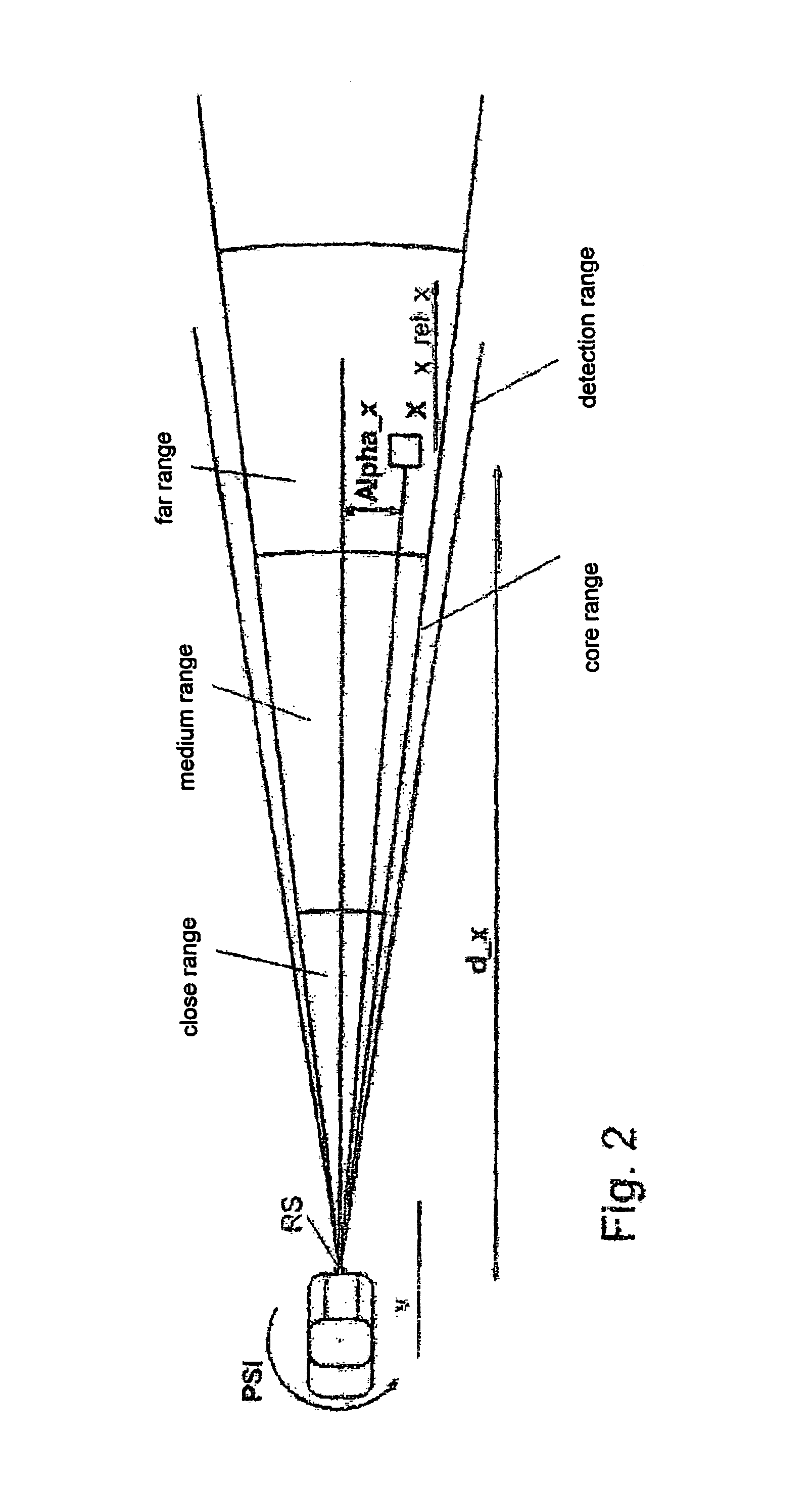
[0106]The radar sensor RS generates signals characteristic of objects located in the area in front of the motor vehicle in the direction of travel of the motor vehicle, which are fed to the electronic control unit ECU and therein further processed in a way described further below. Furtherm...


PUM


Abstract

System for evaluating the driving environment of a motor vehicle and for influencing the speed of the motor vehicle in its own lane, with an electronic control unit, which is connected to a signal generator generating a signal which is characteristic of the desired speed of the motor vehicle, a signal generator generating a signal which is characteristic of the yaw rate of the motor vehicle about its vertical axis, a signal generator which generates, for objects located in the space lying in front of the motor vehicle in its direction of travel, a signal which is characteristic of the distance and orientation of the objects with respect to the motor vehicle and which reproduces the speed relative to the speed of the driver's motor vehicle, and / or the distance relative to the driver's motor vehicle, and / or the angular offset or the lateral deviation relative to the vehicle longitudinal axis of the driver's motor vehicle, and a signal generator generating a signal which is characteristic of the speed at least of one wheel of the motor vehicle, and which unit is connected to at least one control device influencing the road behavior of the motor vehicle in order to supply this with output signals which are derived from the road behavior of the motor vehicle located in front of the driver's motor vehicle, with characteristic values having fluid boundaries being established in the electronic control unit for at least two different road environments (town traffic, country road, motorway) in order to distinguish the type of road on which the driver's motor vehicle is traveling, wherein a quantity influencing the respective characteristic value is the “environmental speed” established from the speeds of the objects detected in the space in front of the driver's motor vehicle and preferably determined by averaging.

Description

CROSS REFERENCE TO RELATED APPLICATION[0001]This application is a continuation of application number PCT / EP03 / 013026 filed Nov. 20, 2003, the disclosures of which are incorporated herein by reference, which claims priority to German Application No. 102 54 421.2 filed Nov. 21, 2002, the disclosures of which are incorporated herein by reference.BACKGROUND OF THE INVENTION[0002]The invention relates to a system for influencing the speed of a motor vehicle. Control systems of this kind are increasingly being used in motor vehicles, in particular upper and upper medium class private cars, under the name of ACC (Autonomous / Adaptive Cruise Control).[0003]Devices are known which control the driving speed of a motor vehicle, wherein the driver can preset a desired speed and the driving speed of the motor vehicle is brought to this target speed by a speed controller and kept there all the time this device is activated. However, no monitoring of the driving speed of a motor vehicle traveling a...

Claims


Application Information

Patent Timeline
Patent Type & Authority Patents(United States)
IPC IPC(8): G06F7/00B60T7/12B60K31/00B60W30/16G01S13/42G01S13/72G01S13/931G08G1/16
CPCB60K31/0008B60W30/16G01S13/723G01S13/931G08G1/16G08G1/161G01S2013/9375B60T2201/081B60W2520/125B60W2520/14B60W2550/141B60W2550/20B60W2550/306G01S13/426G01S2013/9321G01S2013/9325G01S2013/935G01S2013/9353G01S2013/9364G01S2013/9367G01S2013/9357G01S2013/9346B60T2201/08G08G1/166G08G1/167G01S2013/9319G01S2013/9322G01S2013/9324G01S2013/93185G01S2013/9323G01S2013/932G01S2013/93271B60W2554/4041B60W2552/05B60W2554/00B60W2554/802B60W2552/10
Inventor SCHRODER, MARKO
Owner LUCAS AUTOMOTIVE GMBH
Why Eureka
Try Eureka