Power consumption control method and information processing device

a power consumption control and information processing technology, applied in the direction of liquid/fluent solid measurement, process and machine control, instruments, etc., can solve the problems of increasing power consumption, increasing size, increasing cost, etc., and achieve the effect of reducing system power consumption with certainty and low power capacity

Inactive Publication Date: 2007-02-13
KK TOSHIBA
View PDF17 Cites 53 Cited by
  • Summary
  • Abstract
  • Description
  • Claims
  • Application Information

AI Technical Summary

Benefits of technology

[0008]It is an object of the present invention to provide a power consumption control method and an information processor that permit the system power consumption to be reduced with certainty and an AC adapter or battery pack of low power capacity to be used.
[0009]According to an aspect of the present invention, there is provided a power consumption control method that calculates an average power consumption on the basis of the power consumption of a system including a CPU; and reduces the power consumption of the CPU when the average power consumption exceeds a specified value.
[0010]According to another aspect of the present invention, there is provided an information processing device having: a CPU; and a controller that calculates an average power consumption of a system and controls to reduce power consumed by the CPU when the average power consumption exceeds a predetermined value.

Problems solved by technology

With recent general personal computers, however, the power consumption has been increasing as the processing power of CPUs increases.
For this reason, an AC adapter / battery pack of higher capacity will be required, which may result in problems of increased cost, increased size, and elevated temperature of the case surface.

Method used


Image

  • Power consumption control method and information processing device
  • Power consumption control method and information processing device
  • Power consumption control method and information processing device

Examples


first embodiment

[0020][First Embodiment]

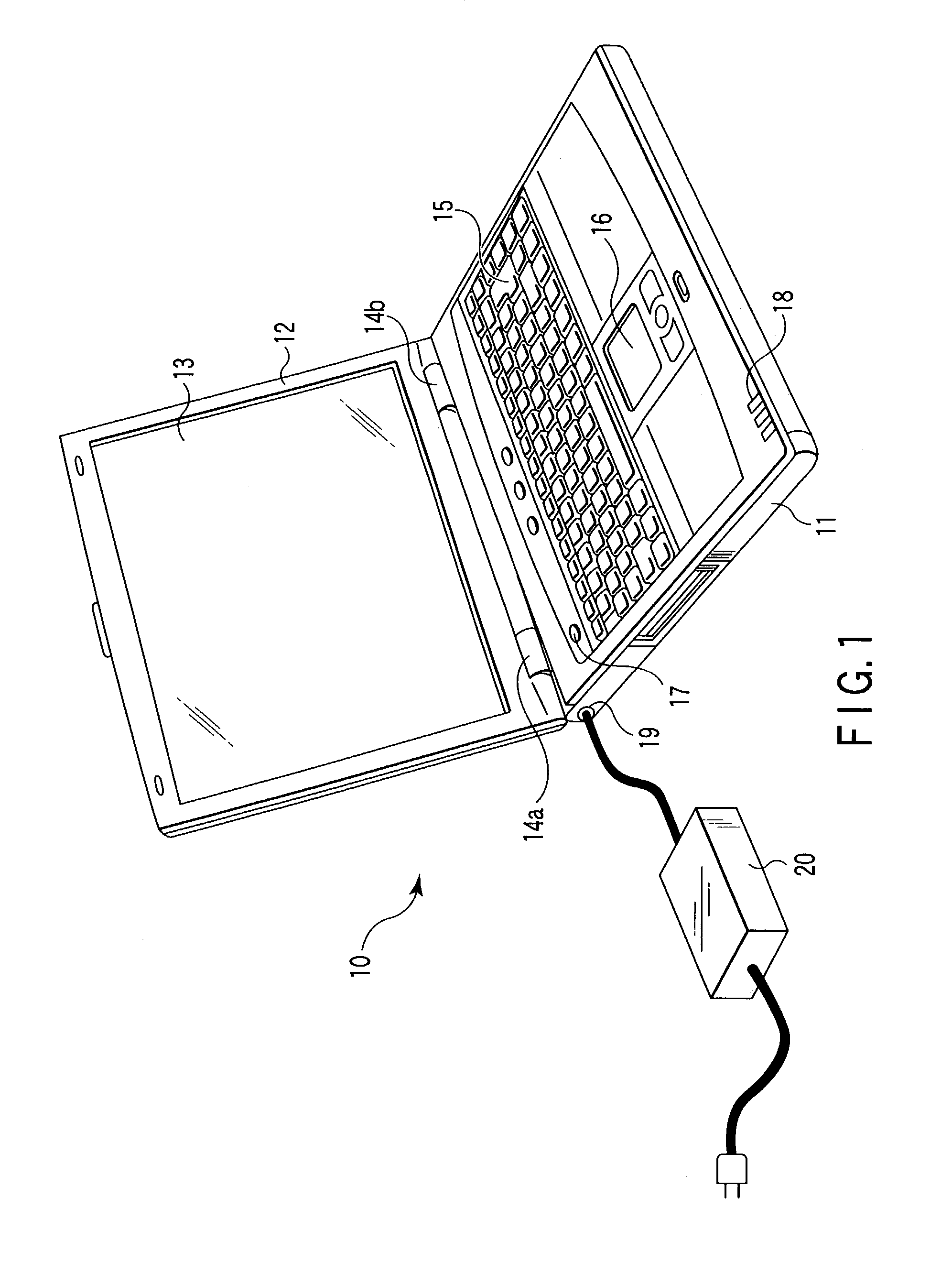
[0021]FIG. 1 is a perspective view of a notebook personal computer. In FIG. 1, the personal computer 10 comprises a case body 11 and a lid 12. The lid 12 houses an LCD (liquid crystal display) panel 13 as an example of a display device. The lid 12 is held so that the lid 12 can be flipped over with hinges 14a and 14b at the rear edge of the case body 11.

[0022]The case body 11 is provided on top with a keyboard (KB) 15, a touch pad 16, a power switch 17, a status display LED 18, etc. Also, the case body is provided with a jack 19 on its left side, into which a plug connected to an AC adapter 20 is inserted. The AC adapter 20 converts an externally applied AC (alternating current) voltage into a DC (direct current) voltage for application to the computer. Further, circuit boards, a battery pack and so on are housed in the case body 11.

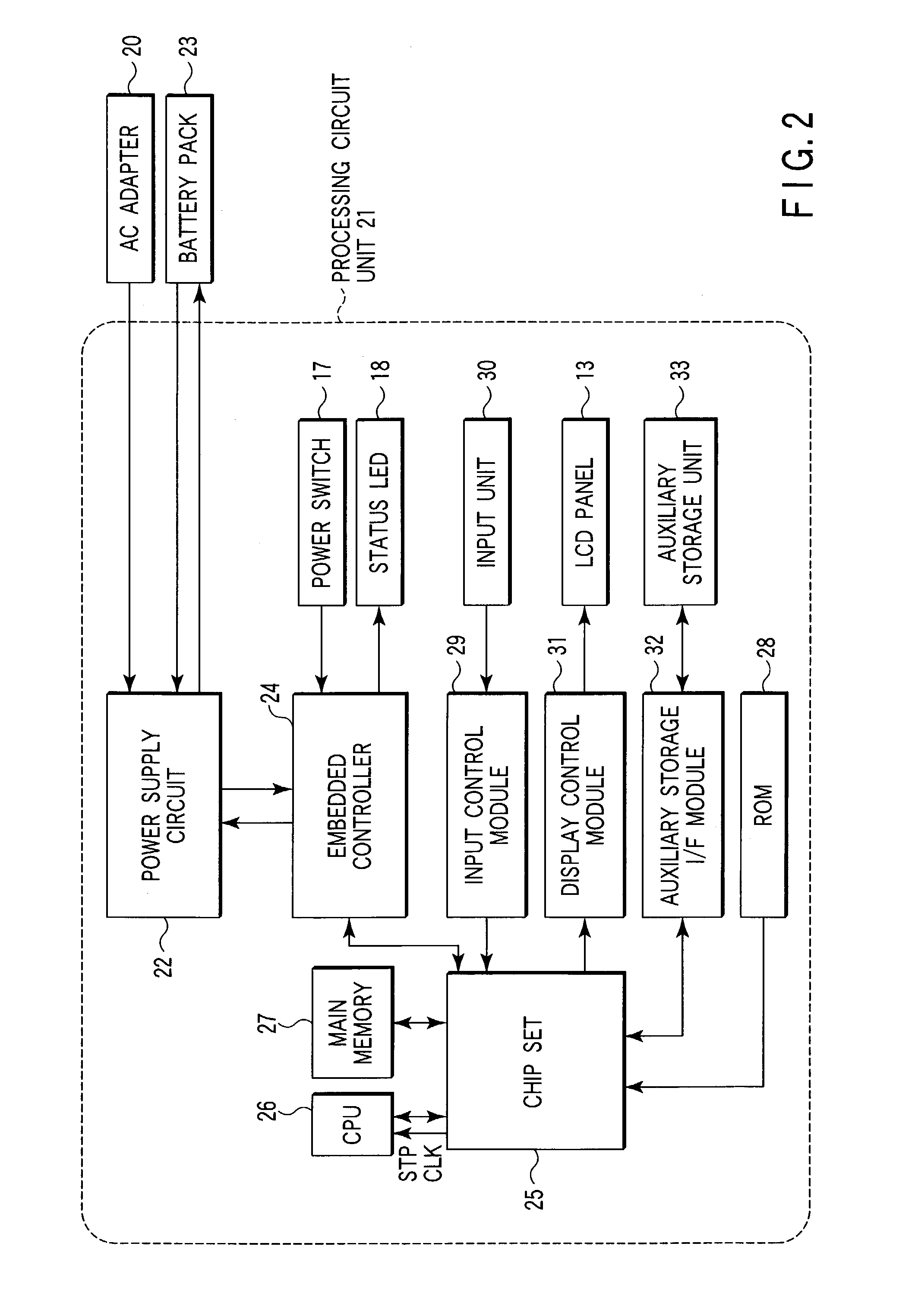
[0023]FIG. 2 is a block diagram of the personal computer 10.

[0024]In FIG. 2, a processing circuit unit 21 is provided with a pow...

second embodiment

[0053][Second Embodiment]

[0054]A second embodiment of the present invention will be described next with reference to FIG. 5, which illustrates, in block diagram form, a personal computer according to the second embodiment of the present invention.

[0055]In the first embodiment, the embedded controller 24 is used for throttling control of the CPU 26. In the second embodiment, unlike the first embodiment, a current detecting circuit 50 is placed to detect a system-consumed current in the power supply circuit 22 and the on-off control of throttling of the CPU 26 is effected by that current detecting circuit 50 according to the system current. The configuration of FIG. 5 is the same as that of the first embodiment shown in FIG. 2 except for the arrangement of the current sensor 50. In FIG. 5, therefore, components corresponding to those in FIG. 2 are denoted by like reference numerals and detailed descriptions thereof are omitted.

[0056]The current detecting circuit 50 is constructed, as ...

third embodiment

[0061][Third Embodiment]

[0062]A third embodiment of the present invention will be described next. The third embodiment is directed to a configuration such that, when the notebook personal computer shown in FIGS. 1 and 2 is battery-powered, the user is allowed to set a battery operating time. In this case, the user can specify the battery operating time set mode through the input device 30.

[0063]FIG. 7 is a flowchart for the process when the user sets a battery operating time. When the user specifies the battery operating time set mode through the input device 30 (step B1), the CPU 26 checks a residual power of the battery pack 23 through the embedded controller 24 and then calculates a maximum battery operating time under conditions of throttling control (step B2).

[0064]The CPU 26 sets or reads out from a database two or more candidates for the battery operating time within the range of the maximum battery operating time and displays them on the display screen so that the user can m...


PUM


Abstract

A controller reads a current value from a current sensor at regular intervals and calculates the average power consumption (Pavg) for a specified length of time (T). When the average power consumption (Pavg) exceeds an upper value (Pu) of power consumption, the controller performs throttling control of a CPU at a throttling rate of r %. If, nevertheless, the average power consumption (Pavg) is above the upper value (Pu), the controller sequentially increases the throttling rate in steps of r %. When the average power consumption (Pavg) is reduced below a lower value (Pl) as a result of the throttling control, the controller sequentially decreases the throttling rate in steps of r % until the upper value (Pu) is reached.

Description

CROSS-REFERENCE TO RELATED APPLICATIONS[0001]This application is based upon and claims the benefit of priority from prior Japanese Patent Application No. 2002-100462, filed Apr. 2, 2002.BACKGROUND OF THE INVENTION[0002]1. Field of the Invention[0003]The present invention relates to a power consumption control method and an information processing device that reduce the power consumption of a system.[0004]2. Description of the Related Art[0005]Conventionally, in information processors, in particular notebook personal computers, a maximum power consumption of the system as a whole is generally estimated during system design. An AC adapter or battery pack is used that has a power capacity that allows for the estimated maximum power consumption. Likewise, in desktop personal computers as well, the maximum power consumption of the system as a whole is estimated during system design and the AC adapter is used that has a power capacity that allows for the estimated maximum power consumption...

Claims


Application Information

Patent Timeline
Patent Type & Authority Patents(United States)
IPC IPC(8): G06F1/26G06F1/32
CPCG06F1/3203G06F1/324Y02B60/1217Y02D10/00
Inventor NAKAZATO, TAKAHIRO
Owner KK TOSHIBA
Why Eureka
Try Eureka