
Press forming apparatus for fuel cell metal separator

a technology of metal separator and press forming method, which is applied in forging/pressing/hammering apparatus, forging presses, electrochemical generators, etc., can solve the problems of excessive elongation of the circumference creases and warps, and shallow groove depth, so as to prevent swelling of the center portion of the separator material, good sealing characteristics, and good size accuracy

Active Publication Date: 2007-02-20
HONDA MOTOR CO LTD
View PDF11 Cites 22 Cited by
  • Summary
  • Abstract
  • Description
  • Claims
  • Application Information

AI Technical Summary

Benefits of technology

The apparatus ensures accurate size and shape retention of the separator, facilitating easier integration into a die and achieving superior sealing characteristics when separators are stacked.

Problems solved by technology

As a result, creases and warps are formed, the circumference of the separator material is excessively elongated, and groove depth is shallow.
Due to this, after a subsequent trimming process is performed, creases, etc., are maintained as they are, and good size accuracy is not thereby obtained at each portion of the separator.
Therefore, when a seal is integrally formed with the separator, setting of the separator in a die is difficult.
When separators are stacked in a stack, good sealing characteristics between separators cannot be obtained.

Method used


Image

  • Press forming apparatus for fuel cell metal separator
  • Press forming apparatus for fuel cell metal separator
  • Press forming apparatus for fuel cell metal separator

Examples


Embodiment Construction

[0021]A preferred embodiment of the present invention will be described hereinafter with reference to the Figures.

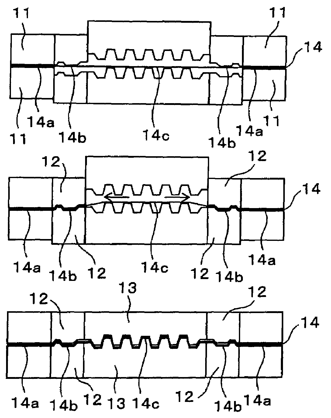
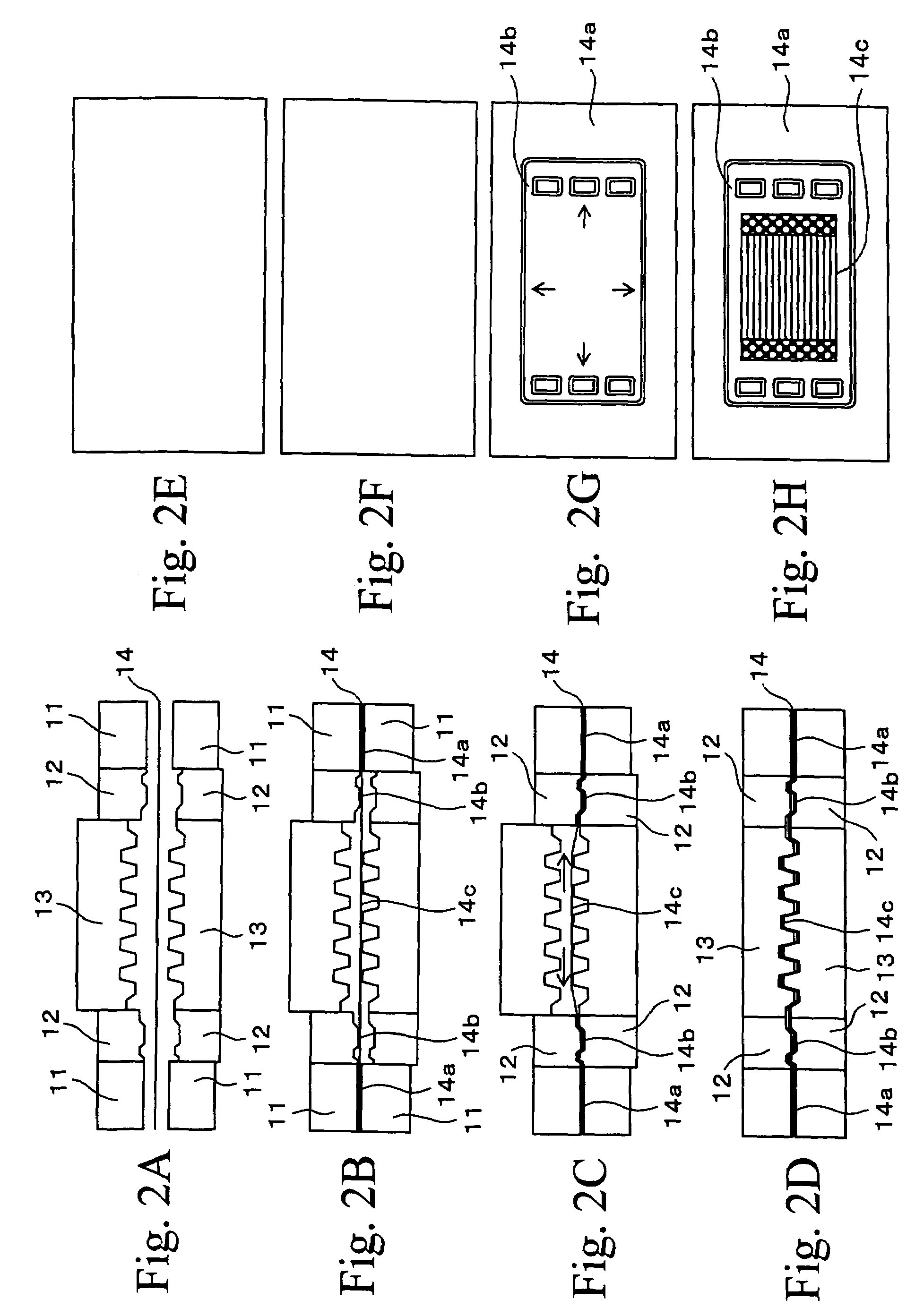
[0022]FIGS. 2A to 2D are side views showing in time series a press forming apparatus for metal separators for fuel cells and a separator material of the present invention, and FIGS. 2E to 2H are plane views showing conditions of the separator materials corresponding to FIGS. 2A to 2D. In FIGS. 2C and 2G, arrows denote a direction of stress generated in the separator material.

[0023]A press forming apparatus for metal separators for fuel cells shown in FIG. 2A has a pair of peripheral portion holding dies 11, a pair of intermediate portion forming dies 12 disposed inside the peripheral portion holding dies 11, and a pair of center portion forming dies 13 disposed inside the intermediate portion forming dies 12. The peripheral portion holding dies 11 hold a peripheral portion of a separator material and are movable toward and counter to each other. The intermediate portion ...


PUM

PropertyMeasurementUnit
structureaaaaaaaaaa
metallographic structureaaaaaaaaaa
shapeaaaaaaaaaa

Abstract

A press forming apparatus, for metal separators for fuel cells, has a pair of peripheral portion holding dies which hold a peripheral portion of a material and are movable toward and counter to each other; a pair of intermediate portion forming dies for forming a intermediate portion of the material, which are disposed inside the peripheral portion holding dies and are movable toward and counter to each other; and a pair of center portion forming dies for forming a center portion of the material, which are disposed inside the intermediate portion forming dies and are movable toward and counter to each other, wherein one of the peripheral portion holding dies and one of the intermediate portion forming dies are fixed to each other, one of the center portion forming dies is movable with respect to one of the intermediate portion forming dies toward the material, the other intermediate portion forming die and the other center portion forming die are fixed to each other, and the other intermediate portion forming die is movable with respect to the other peripheral portion holding die.

Description

BACKGROUND OF THE INVENTION[0001]1. Field of the Invention[0002]The present invention relates to a press forming apparatus and to a press forming method for producing metal separators for fuel cells. In particular, the present invention relates to a press forming technique for producing metal separators for high precision solid polymer electrolyte fuel cells, which facilitates setting a solid polymer electrolyte fuel cell metal separator in a die when a seal is integrally formed with the metal separator, and which yields a good sealing characteristics between separators when separators are stacked in a stack.[0003]2. Description of the Related Art[0004]In solid polymer electrolyte fuel cells, a separator is applied to both sides of a plate-shaped electrode (MEA: Membrane Electrode Assembly) to form a unit having a layered structure, and plural units are stacked to form a fuel cell stack. The MEA is a three-layered structure in which a polymerized electrolytic membrane, which is made...

Claims


Application Information

Patent Timeline
Patent Type & Authority Patents(United States)
IPC IPC(8): B21D13/02H01M8/02B21D22/02H01M8/10
CPCB21D13/02B21D22/02H01M8/0206H01M8/0263H01M8/0254Y02E60/50H01M2008/1095
Inventor ENJOJI, NAOYUKIKAWAMURA, TOSHIKIKIKUCHI, HIDEAKIMONDA, TAKANORI
Owner HONDA MOTOR CO LTD
Learn More