Display rack construction

a display rack and construction technology, applied in the field of display rack construction, can solve the problems of difficult to remove any items from the hook, unfavorable display technique, unfavorable display arrangement, etc., and achieve the effect of convenient placement, stable display rack construction, and easy disassembly

Inactive Publication Date: 2007-02-20
LIBMAN
View PDF12 Cites 41 Cited by
  • Summary
  • Abstract
  • Description
  • Claims
  • Application Information

AI Technical Summary

Benefits of technology

[0008]There is further included in the construction a bracket assembly that simultaneously may engage both the first and second grid assemblies and hold those assemblies juxtaposed in a desired position. Hook members projecting from the bracket assembly engage the horizontal rod members of the respective first and second grid assemblies and effectively interlock with the horizontal rod members to simultaneously support the bracket assembly and securely retain the grid assemblies in their side-by-side position. The combination of grid assemblies and bracket assembly provide a generally stable display rack construction by limiting lateral movement of the grid assemblies and avoids the need for ancillary connectors to secure the side rods of adjacent grid assemblies together is spaced relation. The bracket assembly also includes projecting rod members which extend in a cantilever manner from the hook members and are spaced so as to facilitate the placement between the projecting rod members of handles associated with items to be displayed.
[0009]Because the bracket assembly is designed to simultaneously support or engage handle members as well as retain the grid assemblies in position with respect to one another, the bracket assembly may be easily disassembled. As a result, uniform size grid assemblies may be utilized in the manufacture of the display rack. Further, the bracket assembly may be adjusted to engage with variously positioned horizontal rod members associated with the grid assemblies to accommodate various sizes and heights of items maintained in the display rack. Also, multiple bracket assemblies may be used, and the bracket assemblies may be designed to hold, support and / or display a myriad of items of different sizes and shapes, including but not limited to brooms, mops, brushes and the like.

Problems solved by technology

This manner of display is not favored inasmuch as the labeling for the item is typically upside down and thus difficult to read.
Also, such a display technique does not lend itself to ease of access to the displayed item.
Further, arrangement of the displayed items can be difficult, resulting in a non-uniform display arrangement that can appear untidy.
With this arrangement, it is difficult to remove from the hook any items that are not at the front of the row.
Although these types of display racks are deemed useful, maintaining the spaced arrangement of the racks while also providing a stable display support may be difficult and require additional mechanical assembly.
Additionally, when providing such a display rack, the ability to alter the arrangement of the positioning of the displayed items which may vary in size, length and the like is limited by the size and configuration of the ladders.

Method used


Image

  • Display rack construction
  • Display rack construction
  • Display rack construction

Examples


Embodiment Construction

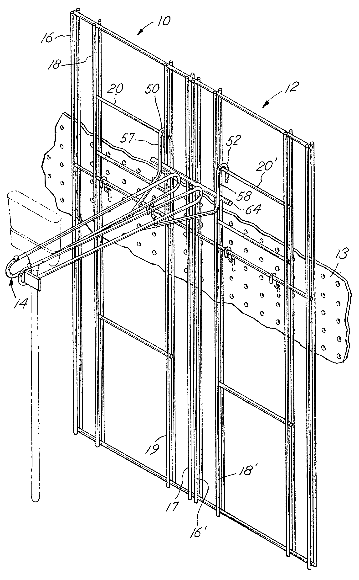
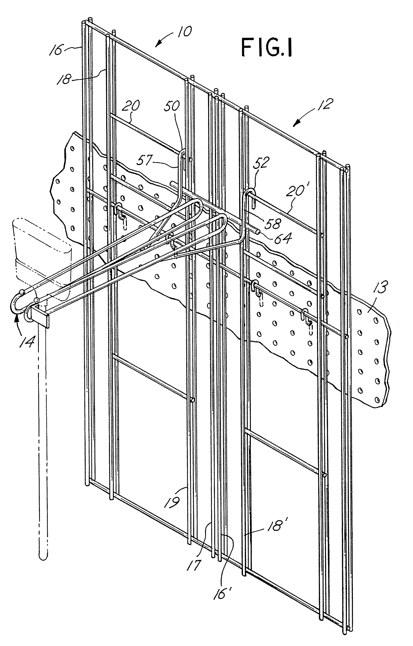
[0017]Referring to FIG. 1, a typical embodiment of the invention comprises at least a first grid assembly 10 and a second grid assembly 12 supported on a vertical surface 13. In practice, the grid assemblies 10 and 12 are substantially identical in construction. However, the grid assemblies 10 and 12 may be altered in construction so long as essential elements or basic elements associated with the construction are incorporated. Additionally, more than two grid assemblies may be utilized in combination to provide a display rack construction. That is, a grid assembly such as assembly 10 and assembly 12 may be duplicated and utilized in multiple combinations to provide a display rack construction. Thus, grid assemblies having the described elemental features may be joined in multiple grid assembly arrays by appropriate bracket assemblies of the type described hereinafter to provide a display rack construction of any desired size.

[0018]The grid assemblies 10 and 12 cooperate with a brac...


PUM


Abstract

A display rack construction includes at least first and second grid assemblies in combination with a removable bracket assembly. The bracket assembly is designed to functionally join the grid assemblies and simultaneously act to support items for purposes of display. The combination of grid assemblies and bracket assembly provides a self-positioning display rack construction that is generally stable with respect to lateral movement of the individual grid assemblies.

Description

BACKGROUND OF THE INVENTION[0001]In a principal aspect, various embodiments of the present invention relate to a display rack construction primarily for the display of items having elongated handles, such as brooms, mops and the like.[0002]The on-site display in retail stores of items that have an elongated handle, such as brooms, mops and other cleaning implements, may be effected in a number of ways. For example, the handles may be inserted downwardly into a free-standing bin with the active end of the item projecting upwardly. This manner of display is not favored inasmuch as the labeling for the item is typically upside down and thus difficult to read. Also, such a display technique does not lend itself to ease of access to the displayed item. Further, arrangement of the displayed items can be difficult, resulting in a non-uniform display arrangement that can appear untidy.[0003]Alternatively, the items may be hung by the handle from hooks on a support rack with a wall or aisle ...

Claims


Application Information

Patent Timeline
Patent Type & Authority Patents(United States)
IPC IPC(8): A47F5/08A47F7/00
CPCA47F5/083A47F5/0815
Inventor LIBMAN, ROBERT
Owner LIBMAN
Why Eureka
Try Eureka