Method and structure for laying communication cable in underground line, and members used for laying

a technology of communication cable and underground line, which is applied in the direction of cables, cables installed in underground tubes, instruments, etc., can solve the problems of large amount of time required for the hook mounting operation, the elongation of the optical fiber cable at breakage is small, and the inability to meet the requirements of the application

Inactive Publication Date: 2007-02-20
ASHIMORI INDS +1
View PDF23 Cites 21 Cited by
  • Summary
  • Abstract
  • Description
  • Claims
  • Application Information

AI Technical Summary

Benefits of technology

[0013]In view of the above mentioned background, it is an object of the present invention to provide a laying method and laying structure for laying optical fiber cables in underground pipelines, and structural members used for the laying, which makes it possible to lay optical fiber cables without applying direct tension on them while preventing their loosening in underground pipelines such as a sewerage pipe, and also to place the communication cables such as optical fiber cables in the upper space of inside the main pipes in which multiple optical fiber cables are laid. It is a secondary object of the present invention to provide a laying method and laying structure for laying communication cables in underground pipelines and structural members used for the laying, which it makes more appropriate to lay communication cables in branch pipes extending from a sewer main pipe.
[0015]a high-strength low-elongation tension member is disposed along each of the trunk communication cables (corresponds to the above mentioned trunk and branch cables) laid in a main pipe and branch communication cables (corresponds to the above mentioned lead-in wire) laid in a branch pipe, the tension member being slidable in the lengthwise direction with respect to each communication cable, and then each communication cable is inserted into the main pipe and the branch pipe by drawing in the trunk tension member placed along the trunk communication cable from one pit to the other pit within the main pipe and the branch tension member placed along the branch communication cable from the foregoing pit to a branch pipe box through the main pipe and the branch pipe, and subsequently each communication cable is laid in the upper space of inside the main pipe by tensioning each tension member thereby stretching tension members inserted in the main pipe substantially straight in the upper space of inside the main pipe, and also the branch communication cable is laid in the branch pipe in such a way that it is prevented from becoming loose by tensioning the branch tension member inserted in the branch pipe.

Problems solved by technology

However, an optical fiber cable has a drawback in that its elongation at breakage is very small because its material is made of glass.
In this conventional technique, however, an optical fiber cable between hooks may sag under its own weight and therefore the spacing between the hooks needs to be relatively short to prevent a creep rupture due to the sag, and therefore a large amount of time is required for the hook mounting operation.
Thus, the robot has a complex structure requiring a high cost.
In this respect, the techniques described in the above publications are not readily adopted.
Furthermore, no consideration so far has been given to the laying of optical fiber cables in branch pipes extending from a sewer main pipe.
For this reason, there are occasions that smooth sewage flow is hindered or optical fibers are damaged.

Method used


Image

  • Method and structure for laying communication cable in underground line, and members used for laying
  • Method and structure for laying communication cable in underground line, and members used for laying
  • Method and structure for laying communication cable in underground line, and members used for laying

Examples


Embodiment Construction

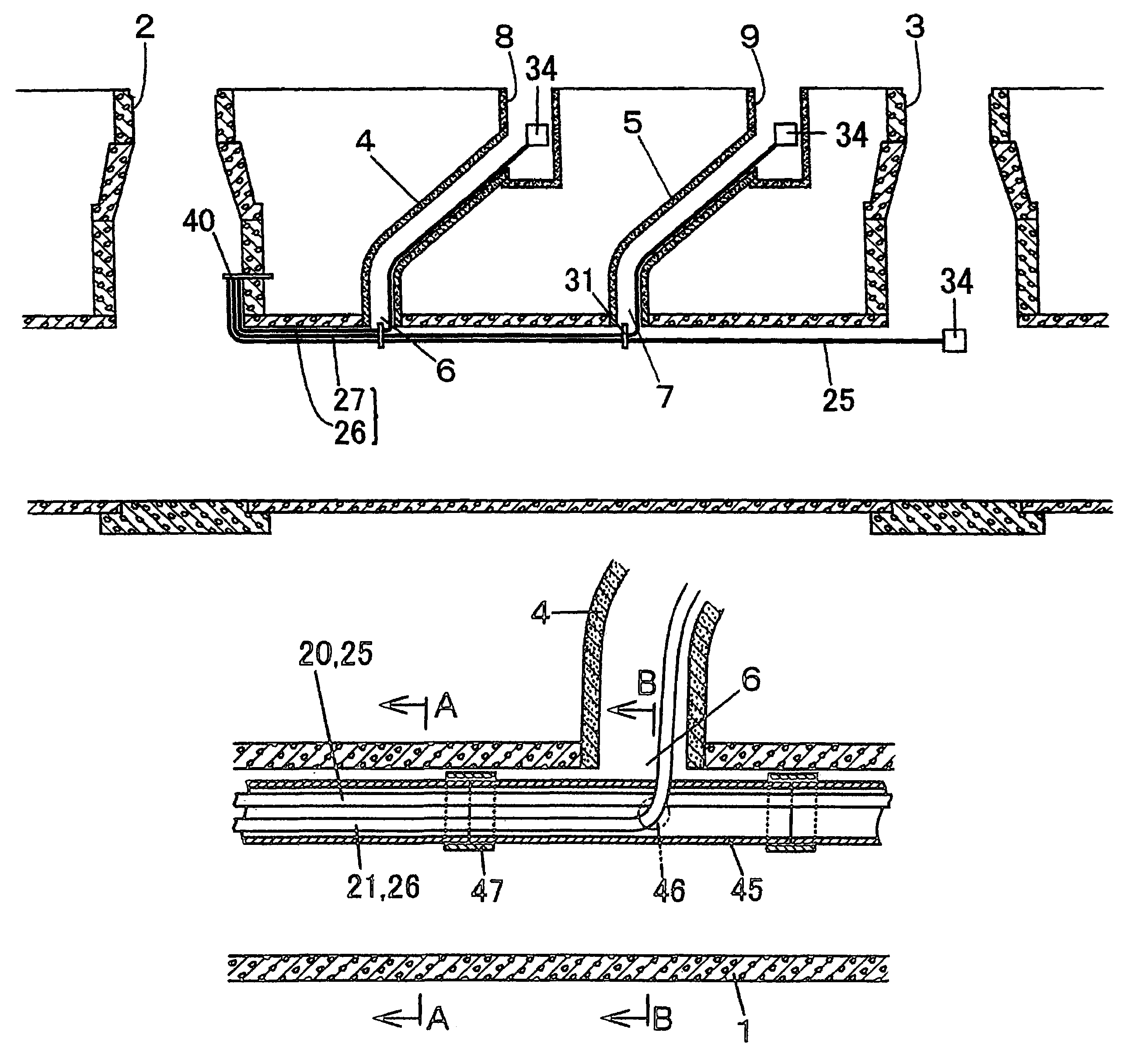
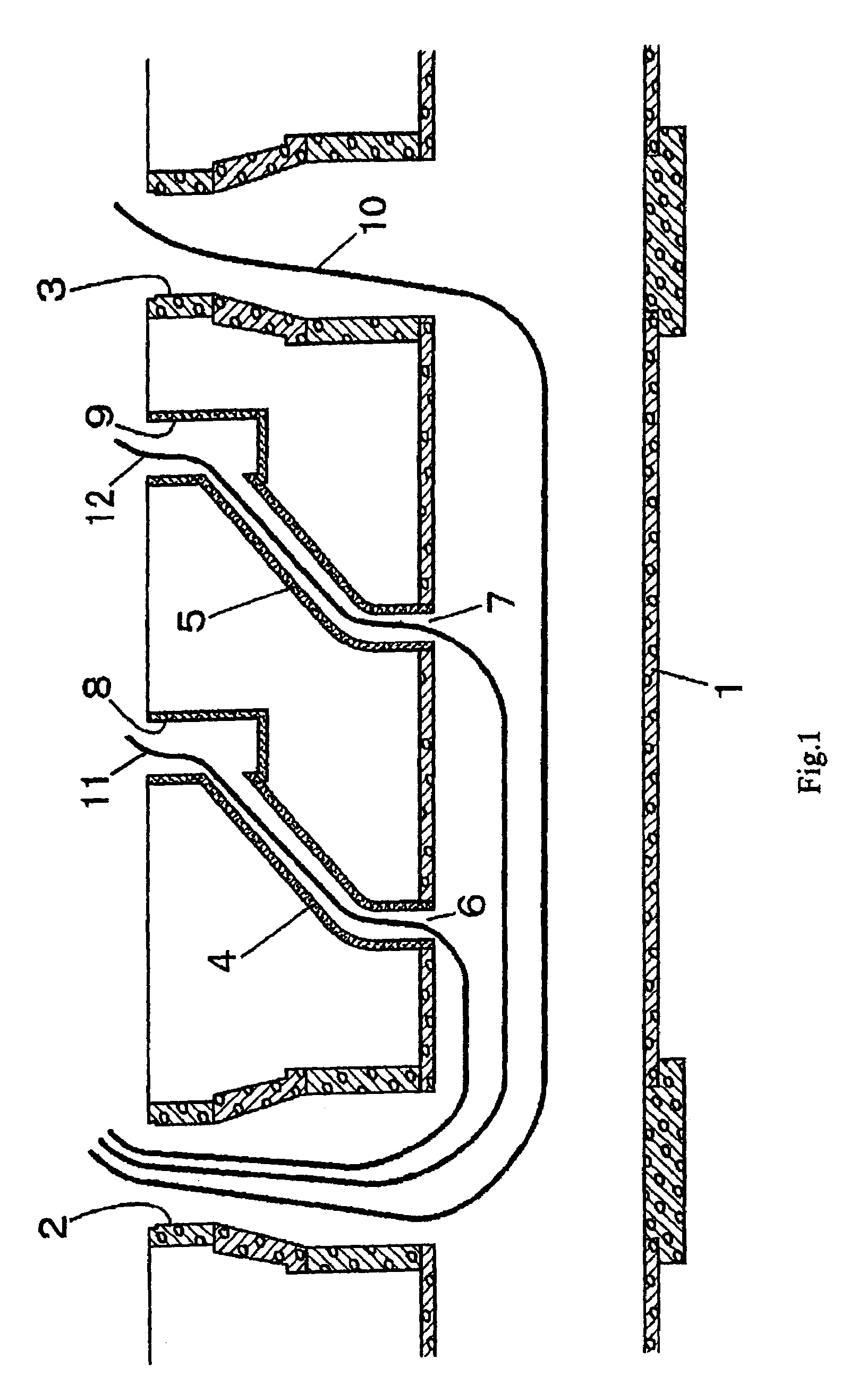
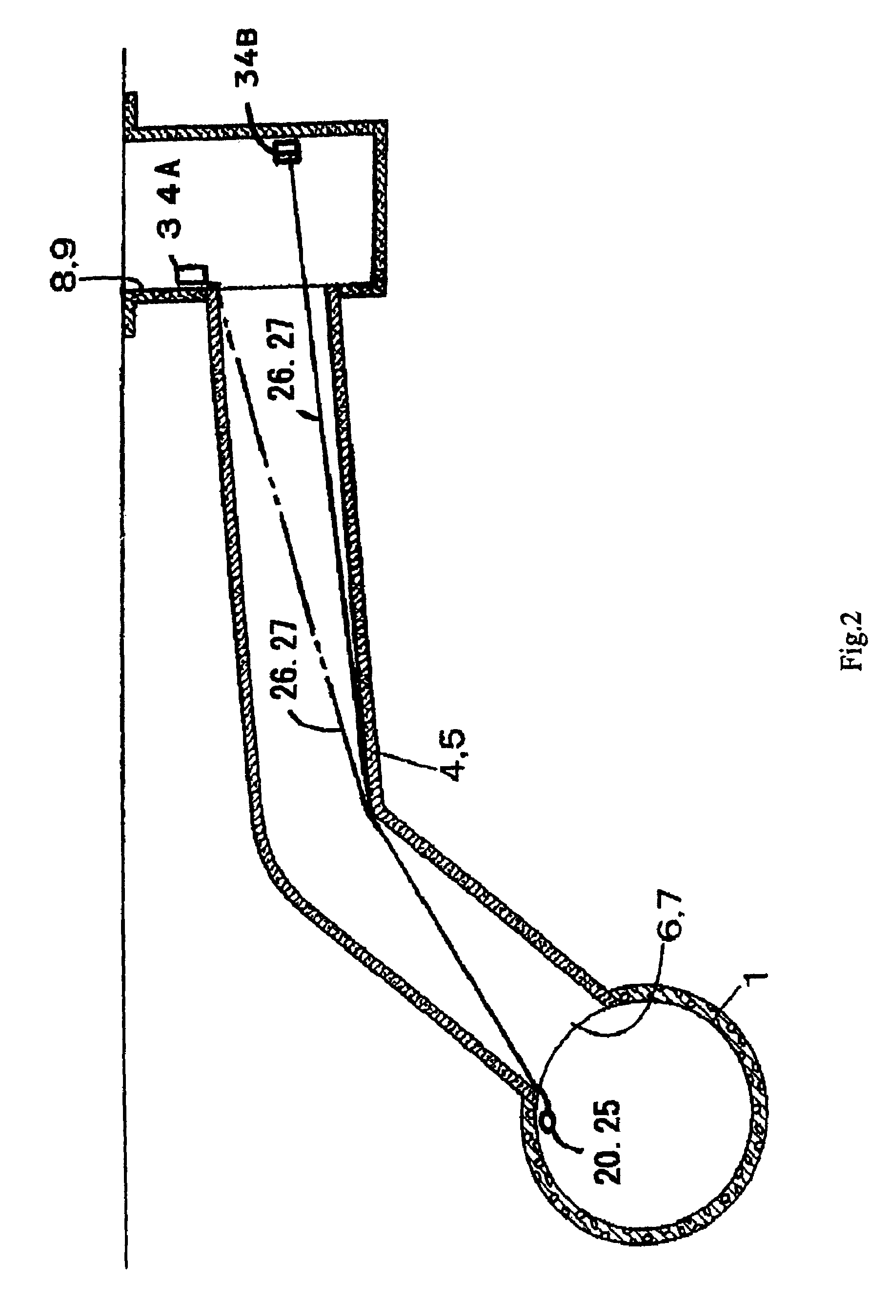
[0184]The embodiments of the present invention will be described below referring to the drawings. In the following description, it is assumed that underground pipelines are a sewer pipeline, but the present invention imposes no limitations on the kinds of pipeline systems or pipes because no jigs such as a hook are not directly attached to the inner surface of the underground pipeline. Potential applications include all kinds of underground pipelines such as gas pipelines laid by steel pipes, water supply pipelines laid by cast iron pipes, storm drain pipelines, and power cable pipelines. When the foregoing pipelines are not provided with manholes which are an existing pit, it is possible to utilize the present invention by installing a new pit. The branch pipe in the present invention means a lateral pipe in sewer pipeline.

[0185]FIG. 1 shows a sewer pipeline as an example of the underground pipeline, the numeral 1 denotes a main pipe of a sewerage pipe laid between a manhole 2 and ...


PUM


Abstract

A laying method for laying communication cables (16) is provided which allows to lay optical fiber cables (20) in an underground pipeline such as a sewage pipe neither placing direct tension nor allowing slack on them, and for a main pipe in which a plurality of optical fiber cables (20) are to be laid, the method also allows to lay optical fiber cables (20) in the upper space of inside the pipeline and to obviate the need of an expensive robot for the laying operation. In the proposed laying method, a high-strength low-elongation tension member is disposed to be slidable in the lengthwise direction along each optical fiber cable (20, 21, 22), and the tension members (25, 26, 27) are drawn into the underground pipeline (1) to tension the trunk tension member (25) thereby stretching the trunk tension member (25) substantially straight in the underground pipeline (1), and thus the optical fiber cables (20, 21, 22) are laid in the upper space of inside the underground pipeline (1). Also the branch tension member (26, 27) is tensioned in the branch pipe (4, 5) to lay the optical fiber cables (21, 22) in the branch pipe without allowing slack.

Description

TECHNICAL FIELD[0001]This invention relates to laying methods, laying structures, and structural members for laying communication cables such as optical fiber cables in underground pipelines, particularly in sewer pipelines.[0002]In recent years, in pursuit of new communication systems, creation of an information and communications network employing optical fiber cables as its transmission medium has been extensively studied. And, as the transmission path, a method of laying optical fiber cables in sewer pipelines, which offer an established communication path to each household, has gained much attention rather than a method of replacing the existing telephone lines with optical fiber cables.BACKGROUND ART[0003]Optical fiber cables are easy to handle and superior in transmission rate and transmission capacity owing to their lightness and flexibility compared to existing metal cables, therefore they are considered to be the likely winner of the competition for a next generation trans...

Claims


Application Information

Patent Timeline
Patent Type & Authority Patents(United States)
IPC IPC(8): F16L7/00F16L3/04G02B6/50H02G1/06H02G1/08H02G9/06
CPCG02B6/502G02B6/508H02G9/06H02G1/08H02G1/06
Inventor SETO, ICHIROTSUCHIYA, FUMIAKIYAGI, ISABUROAZUMA, KATSUHIKOKISHIBE, NOBUYASUASO, KOJIUEDA, YASUHIRO
Owner ASHIMORI INDS
Why Eureka
Try Eureka