Apparatus and method to remove dental implant

a dental implant and applicator technology, applied in the field of dental implants, can solve the problems of reducing the drilling into the implant and and achieve the effects of increasing efficiency, reducing the drilling into the implant and increasing efficiency

Inactive Publication Date: 2007-02-20
KOMETAS ATHAS N
View PDF13 Cites 51 Cited by
  • Summary
  • Abstract
  • Description
  • Claims
  • Application Information

AI Technical Summary

Benefits of technology

[0011]Accordingly, it is an object of the present invention to provide an apparatus and method to remove dental implant which maintains the trephine burr properly aligned with the dental implant so as to avoid drilling into the dental implant during the extraction process. Design features allowing this object to be accomplished include a guide ring sized to slidably fit within a trephine burr bore rotatably attached to a base, and means to attach the base to the implant. Advantages associated with the accomplishment of this object include increased efficiency and reduced drilling into the implant.
[0012]Where an abutment is present, it is another object of the present invention to provide an apparatus and method to remove dental implant which maintains the trephine burr properly aligned with an abutment and dental implant so as to avoid drilling into the abutment and / or dental implant during the extraction process. Design features allowing this object to be accomplished include a guide ring sized to slidably fit within a trephine burr bore rotatably attached to a base, and means to attach the base to the abutment. Advantages associated with the accomplishment of this object include increased efficiency and reduced drilling into the abutment and implant.
[0013]It is another object of the present invention to provide a method to remove dental implant which maintains the trephine burr properly aligned with the dental implant so as to avoid drilling into the dental implant during the extraction process. Method steps to accomplish this include the steps of attaching the apparatus to an implant, sliding a trephine burr bore over a guide ring, and using the guide ring to guide the trephine while drilling into bone in which the implant is implanted, without drilling into the implant or abutment. Advantages associated with the accomplishment of this object include increased efficiency and reduced drilling into the implant.
[0014]Where an abutment is present, it is another object of the present invention to provide a method to remove dental implant which maintains the trephine burr properly aligned with an abutment and dental implant so as to avoid drilling into the abutment and / or dental implant during the extraction process. Method steps to accomplish this include the steps of attaching the apparatus to the abutment, sliding a trephine burr bore over a guide ring, and using the guide ring to guide the trephine while drilling into bone in which the implant is implanted, without drilling into the implant or abutment. Advantages associated with the accomplishment of this object include increased efficiency and reduced drilling into the abutment and implant.
[0015]It is yet another object of this invention to provide an apparatus and method to remove dental implant whose guide ring does not rotate relative to a trephine burr. Design features allowing this object to be achieved include at least one key on a guide ring, and a keyway on a trephine burr bore corresponding to each key sized to slidably admit a key. Benefits associated with reaching this objective include reduced wear between the guide ring and the trephine burr, and hence increased reliability and reduced cost.

Problems solved by technology

Advantages associated with the accomplishment of this object include increased efficiency and reduced drilling into the implant.

Method used


Image

  • Apparatus and method to remove dental implant
  • Apparatus and method to remove dental implant
  • Apparatus and method to remove dental implant

Examples


Embodiment Construction

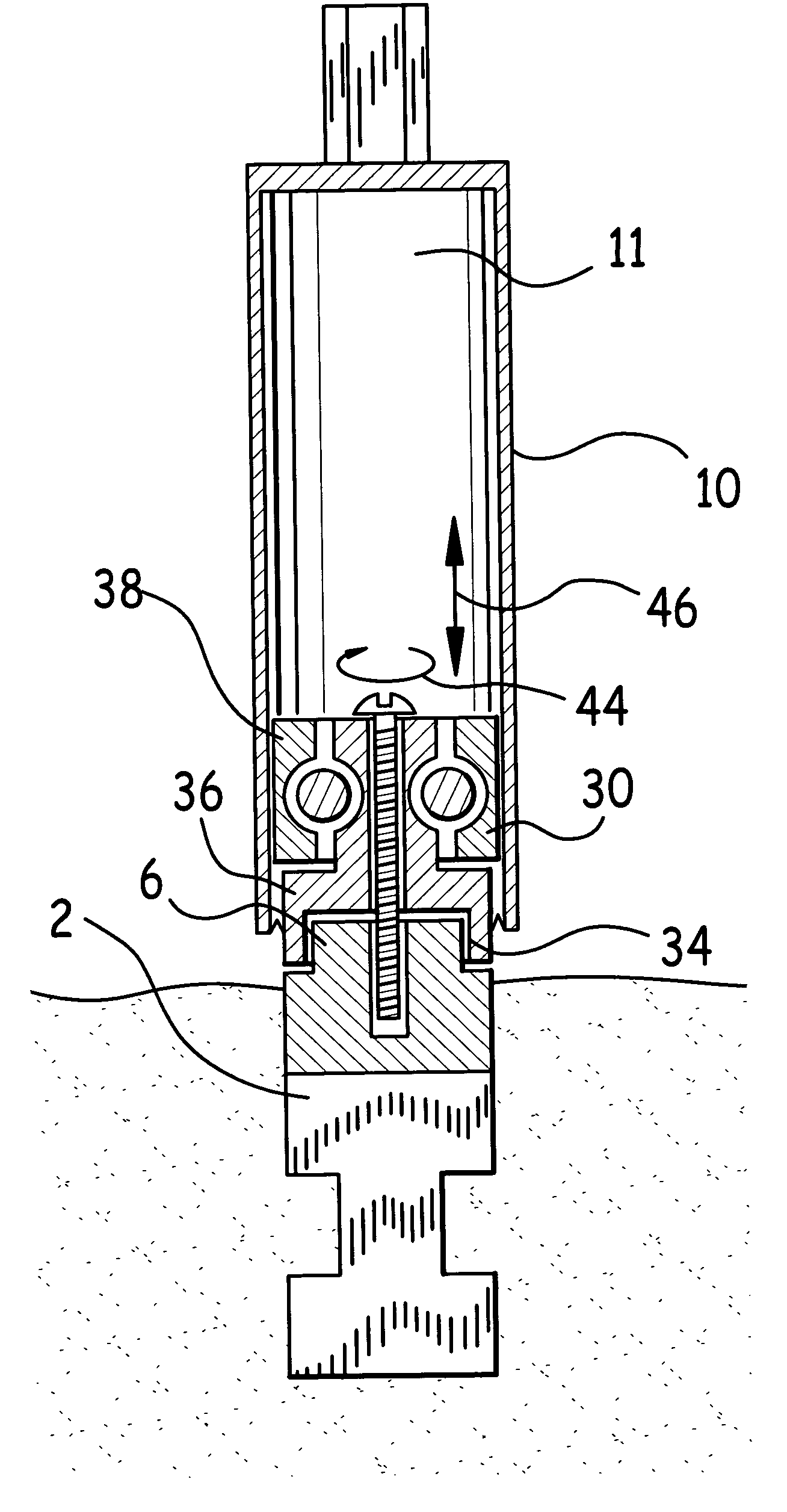
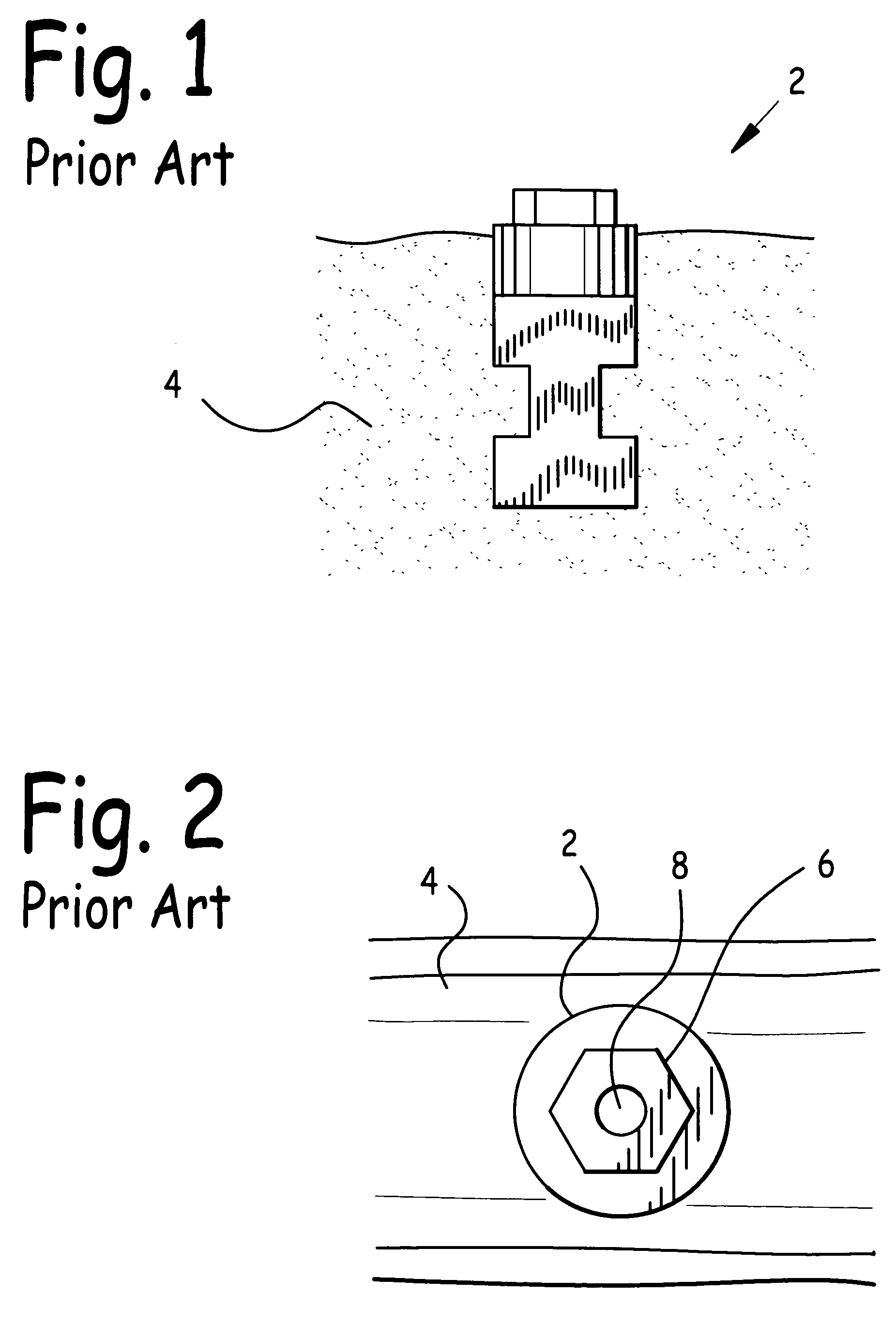
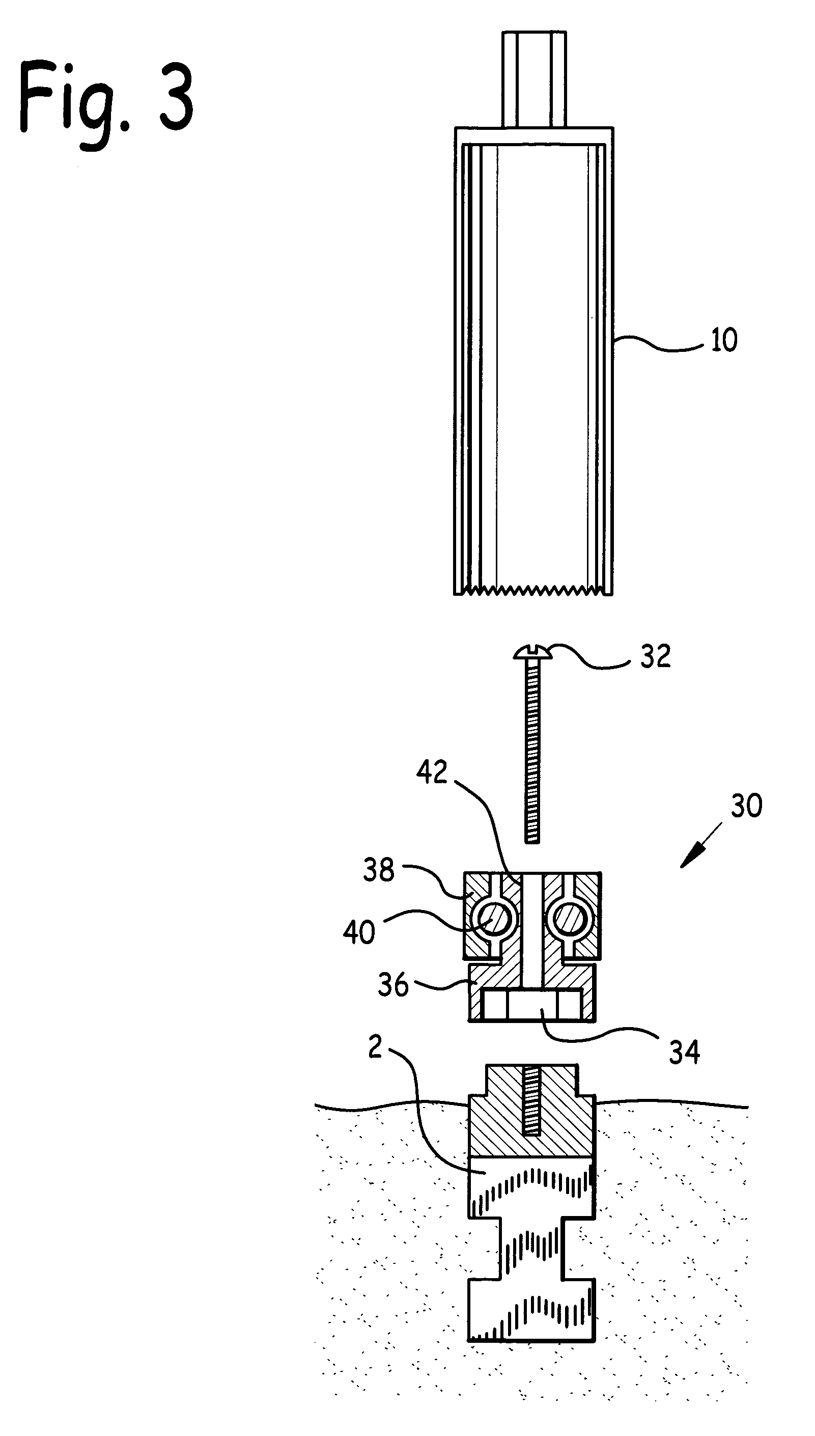
[0033]FIG. 1 is a side isometric view of a prior art implant 2 installed on bone 4. FIG. 2 is a top isometric view of a prior art implant 2 installed in bone 4. Implant 2 comprises implant indexing means 6 and implant connector 8. A prosthesis or abutment 12 to be installed on implant 2 may have a prosthesis or abutment mating indexing means which mates with implant indexing means 6, so as to prevent rotation of the prosthesis or abutment 12 relative to implant 2. While FIGS. 1 and 2 illustrate implant indexing means 6 to be a male hex shape, and the corresponding mating prosthesis or abutment mating indexing means would then be a female hex shape, many different indexing means shapes are used in the industry, including but not limited to different regular and irregular polygonal cross-sectioned indexing means. In addition, implant indexing means 6 could be a female indexing means and the mating abutment or prosthesis indexing means may be male.

[0034]Implant connector 8 is used to a...


PUM


Abstract

A method and apparatus to remove dental implant. The apparatus comprises a guide ring rotatably attached to a base, means to rotatably attach the guide ring to the base, means to attach the apparatus to an implant, and apparatus to remove dental implant indexing means sized to mate with implant indexing means when the apparatus is attached to the implant. Where an abutment is mounted to the implant, means of attaching the base to the abutment is taught. The method includes the steps of attaching the apparatus to an implant or abutment, sliding a trephine burr bore over the guide ring, and using the guide ring to guide the trephine while drilling into bone in which the implant is implanted, without drilling into the implant or abutment.

Description

BACKGROUND OF THE INVENTION[0001]1. Field of the Invention[0002]This invention relates to dental implants, and in particular to an apparatus and method to remove a dental implant.[0003]2. Background of the Invention[0004]Implants in a patient's jaw bone are routinely used in the dentistry arts to anchor individual prosthetic teeth as well as bridges containing a number of prosthetic teeth. As may be observed in FIG. 1, a side cross-sectional view of implant 2, an appropriate aperture is made in bone 4, implant 2 inserted, and then over time bone 4 grows over implant 2, thus securely anchoring it in place.[0005]Referring now also to FIG. 2, a top view of implant 2 in bone 4, implant 2 typically comprises implant indexing means 6, and an implant connector 8. After implant 2 is firmly anchored in bone 4, a prosthesis is attached to it. Implant indexing means 6 is sized to mate with a matching prosthesis indexing means, in order to prevent rotating of the prosthesis relative to implant ...

Claims


Application Information

Patent Timeline
Patent Type & Authority Patents(United States)
IPC IPC(8): A61C3/00
CPCA61C8/0089
Inventor KOMETAS, ATHAS N.
Owner KOMETAS ATHAS N
Why Eureka
Try Eureka