Gear lubrication oil path

A technology of lubricating oil passages and gears, which is applied to engine components, cylinders, cylinder heads, etc., can solve problems such as slow production efficiency, drill bit breakage, and long drilling length, and achieve cost saving, drilling reduction, and effective lubrication. Effect

Inactive Publication Date: 2017-09-15
GUANGXI YUCHAI MASCH CO LTD
View PDF7 Cites 2 Cited by
  • Summary
  • Abstract
  • Description
  • Claims
  • Application Information

AI Technical Summary

Problems solved by technology

like Image 6 and Figure 7 As shown, the gear oil passage 5 of the prior art needs to be formed by drilling holes on the engine body through machining, which leads to the following disadvantages in the prior art: 1. The oil hole needs to be machined, which wastes materials and leads to production failure. The efficiency is slow, and the manufacturing cost is increased; 2. The length of the drilling hole is relatively long, which may easily cause the drill to be out of position and deflect, resulting in the break of the drill
[0003] How to solve the problem of relying on machining in the design of gear lubricating oil circuit, resulting in high cost, slow cycle, and poor workmanship has become an urgent problem in this industry

Method used


Image

  • Gear lubrication oil path
  • Gear lubrication oil path
  • Gear lubrication oil path

Examples


Embodiment Construction

[0018] The specific embodiments of the present invention will be described in detail below in conjunction with the accompanying drawings, but it should be understood that the protection scope of the present invention is not limited by the specific embodiments.

[0019] Unless expressly stated otherwise, throughout the specification and claims, the term "comprise" or variations thereof such as "includes" or "includes" and the like will be understood to include the stated elements or constituents, and not Other elements or other components are not excluded.

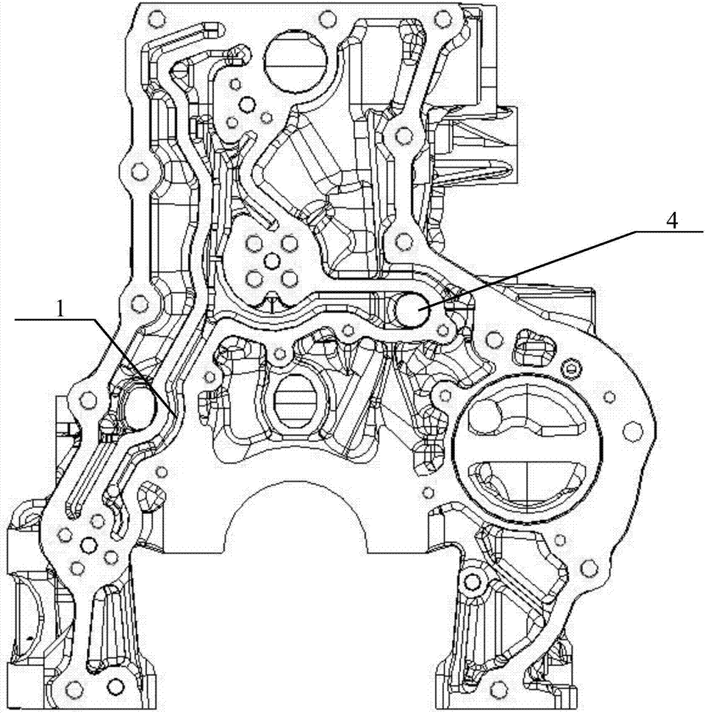
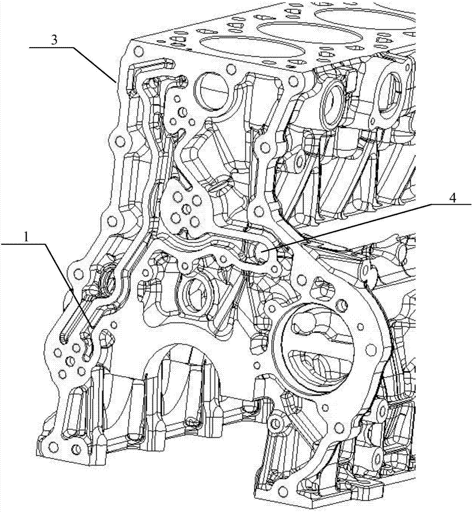
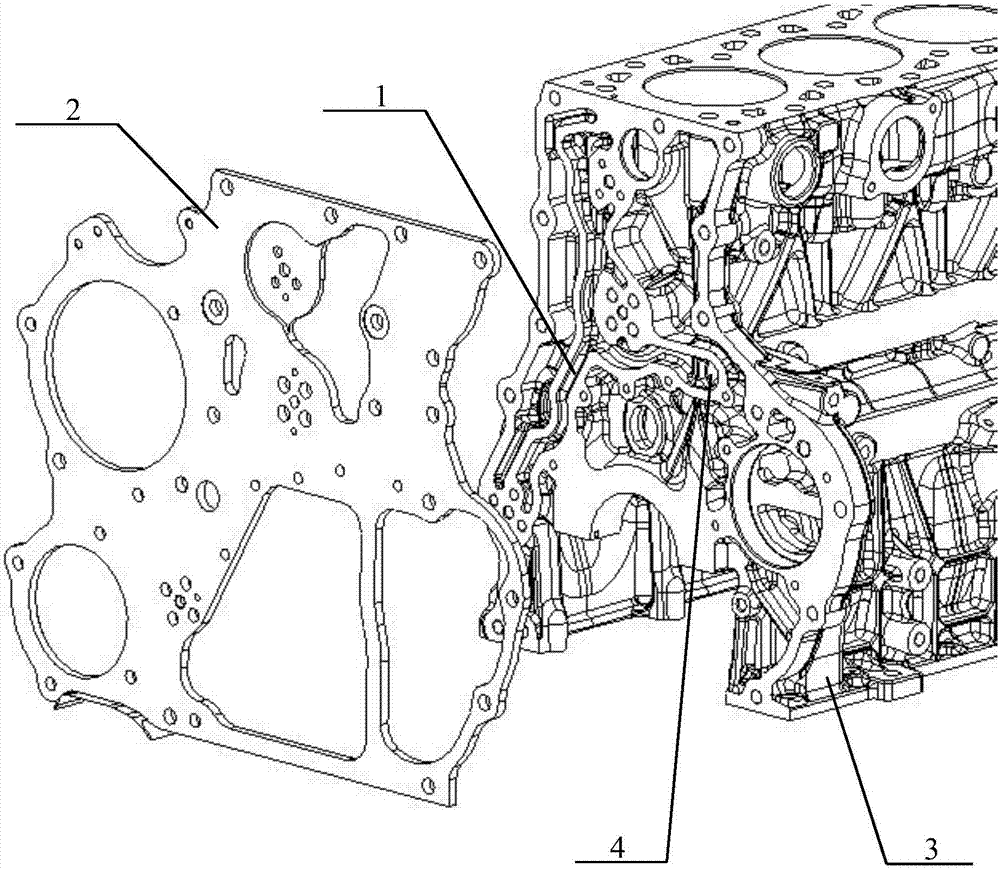
[0020] Such as Figure 1 to Figure 5 As shown, a gear lubricating oil passage according to a specific embodiment of the present invention is applied to the gear lubrication of the engine. The gear lubricating oil passage includes an oil groove 1 cast on the gear mounting end surface of the engine body 3, and the oil groove 1 is connected to the main oil passage 4 of the engine body ; The gear chamber cover plate 2 is seale...


PUM


Abstract

The invention discloses a gear lubrication oil path applied to engine gear lubrication. The gear lubrication oil path comprises an oil groove cast to the gear installing end face of an engine body. The oil groove is connected with a main oil way of the engine body. A gear chamber cover plate covers the gear installing end of the engine body in a covering manner. The gear lubrication oil path is formed through closing of the gear chamber cover plate and the oil groove. The oil groove of the gear lubrication oil path is formed through casting, machining is not needed, the machining abrasion of the engine body is reduced, and gears at multiple positions can be effectively lubricated through a plurality of through holes in the gear chamber cover plate.

Description

technical field [0001] The invention relates to the field of engines, in particular to a gear lubricating oil circuit for gear lubrication of the engine. Background technique [0002] At present, the gear and sliding bearings designed on the machine body are lubricated by internal machining and drilling, and the drilling is connected with the main oil passage to form a closed oil passage. Figure 6 is a schematic diagram of the gear mounting end of an engine block according to the prior art. Figure 7 It is a schematic cross-sectional view of the gear installation end of the engine body according to the prior art. Such as Figure 6 and Figure 7 As shown, the gear oil passage 5 of the prior art needs to be formed by drilling holes on the engine body through machining, which leads to the following disadvantages in the prior art: 1. The oil hole needs to be machined, which wastes materials and leads to production failure. The efficiency is slow, and the manufacturing cost is...

Claims


Application Information

Patent Timeline
Patent Type & Authority Applications(China)
IPC IPC(8): F02F1/20F02F7/00
CPCF02F1/20F02F7/0065
Inventor 廖乾畅徐雪松何化
Owner GUANGXI YUCHAI MASCH CO LTD
Why Eureka
Try Eureka