Deployable and autonomous mooring system

a mooring system and autonomous technology, applied in special-purpose vessels, anchors, buoys, etc., can solve the problems of impracticality in deployment, use and maintenance of such systems, large systems, and complex environment of optical and acoustic transmission, and achieve the effect of reducing the drag on the buoy

Inactive Publication Date: 2007-02-20
THE UNITED STATES OF AMERICA AS REPRESENTED BY THE SECRETARY OF THE NAVY +1
View PDF6 Cites 23 Cited by
  • Summary
  • Abstract
  • Description
  • Claims
  • Application Information

AI Technical Summary

Benefits of technology

[0016]In another embodiment, the present invention provides a buoy having a ratio of length to width of greater than about 2:1 thereby reducing drag on the buoy when placed in a body of water and/or having a shaped

Problems solved by technology

The coupled effects of these characteristics create a complex environment for optical and acoustical transmission, vessel and AUV (autonomous underwater vehicle) operation, remote sensing as well as many other operations.
Thus, such systems are usually large; they have a large surface signature and require a surface vessel for deployment and servicing.
The deployment, use and maintenance of such systems is impractical in a hostile theater far from the United States, where rapid deployment, low observability and autonomous operation are essential.
However, an effective self-mooring system does not exist for an A-sized deployable system.
Hence, the systems are typically left un-moored when they are deployed.
In consequence, the systems may drift with ocean currents, tending to move ashore or out of the area of active interest.
Accordingly, deployment of new systems is frequently required, leading to higher operating costs, and higher risks to Navy assets and personnel.
Although some deployable moorings do exist, they often exceed the “A”-sized dimensional standard.
Further, parachute entang

Method used


Image

  • Deployable and autonomous mooring system
  • Deployable and autonomous mooring system
  • Deployable and autonomous mooring system

Examples


Embodiment Construction

[0035]The present invention is more particularly described in the following description and examples that are intended to be illustrative only since numerous modifications and variations therein will be apparent to those skilled in the art. As used in the specification and in the claims, the singular form “a,”“an,” and “the” may include plural referents unless the context clearly dictates otherwise. Also, as used in the specification and in the claims, the term “comprising” may include the embodiments “consisting of” and “consisting essentially of.”

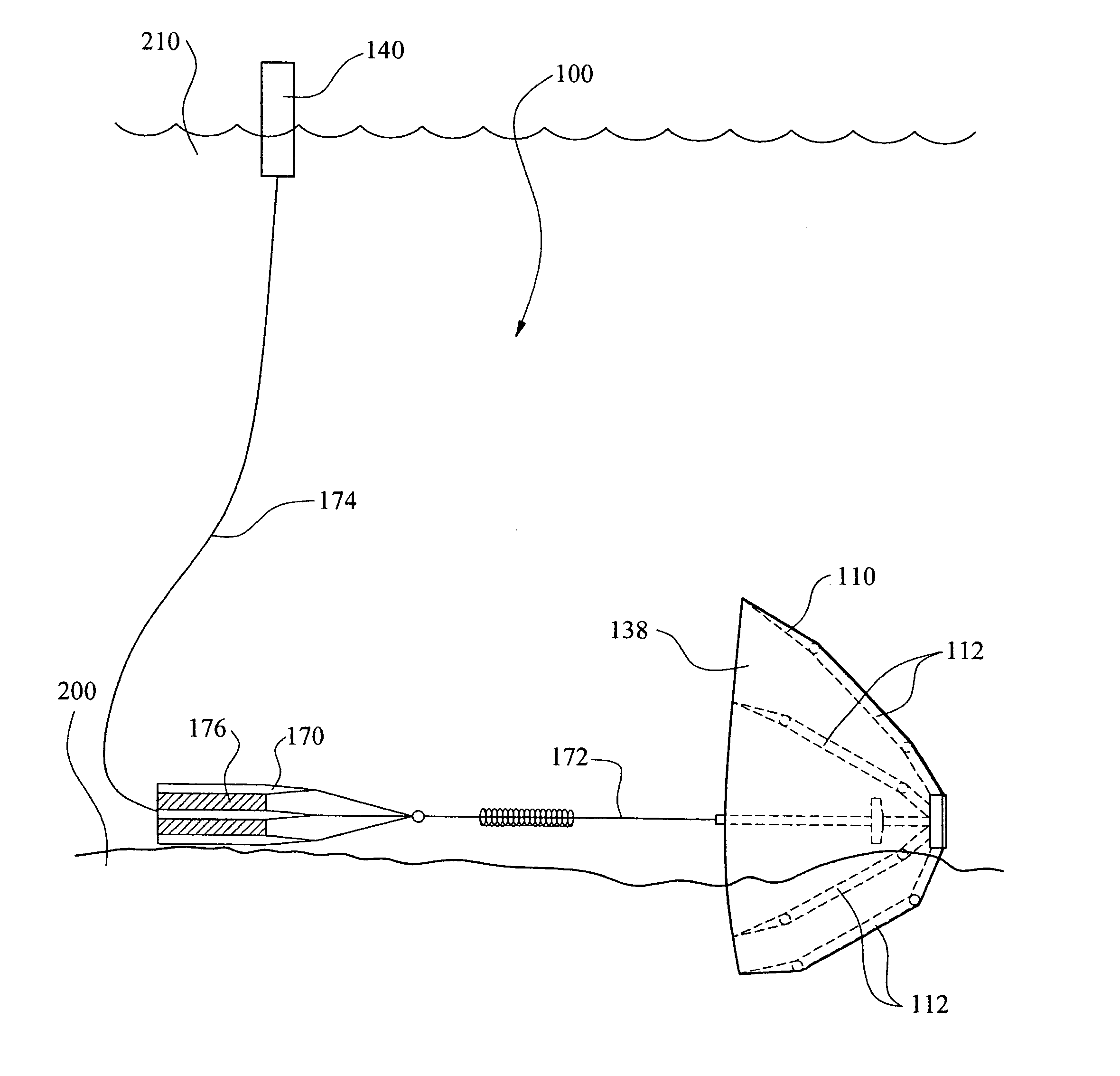
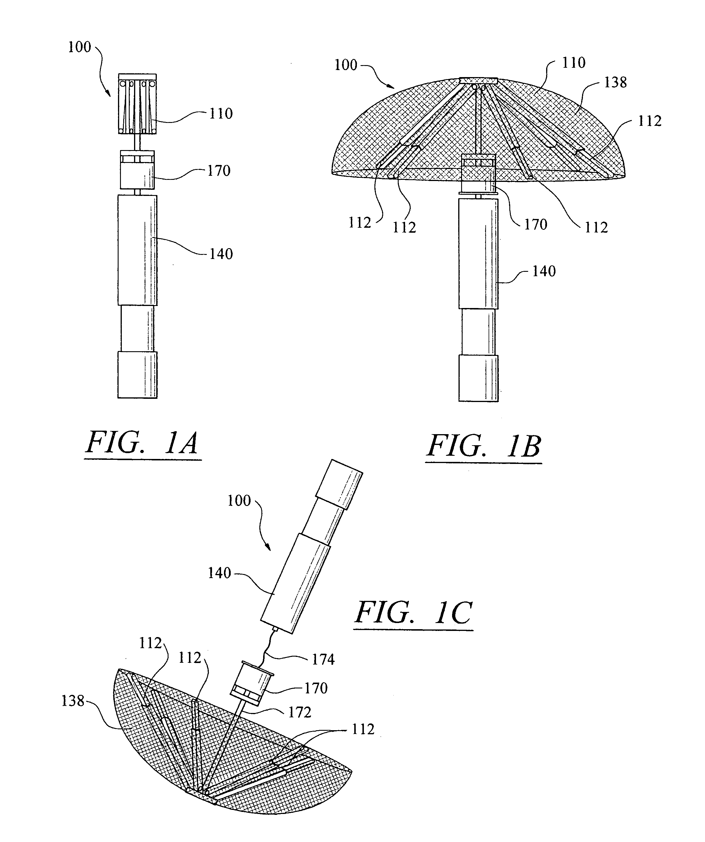
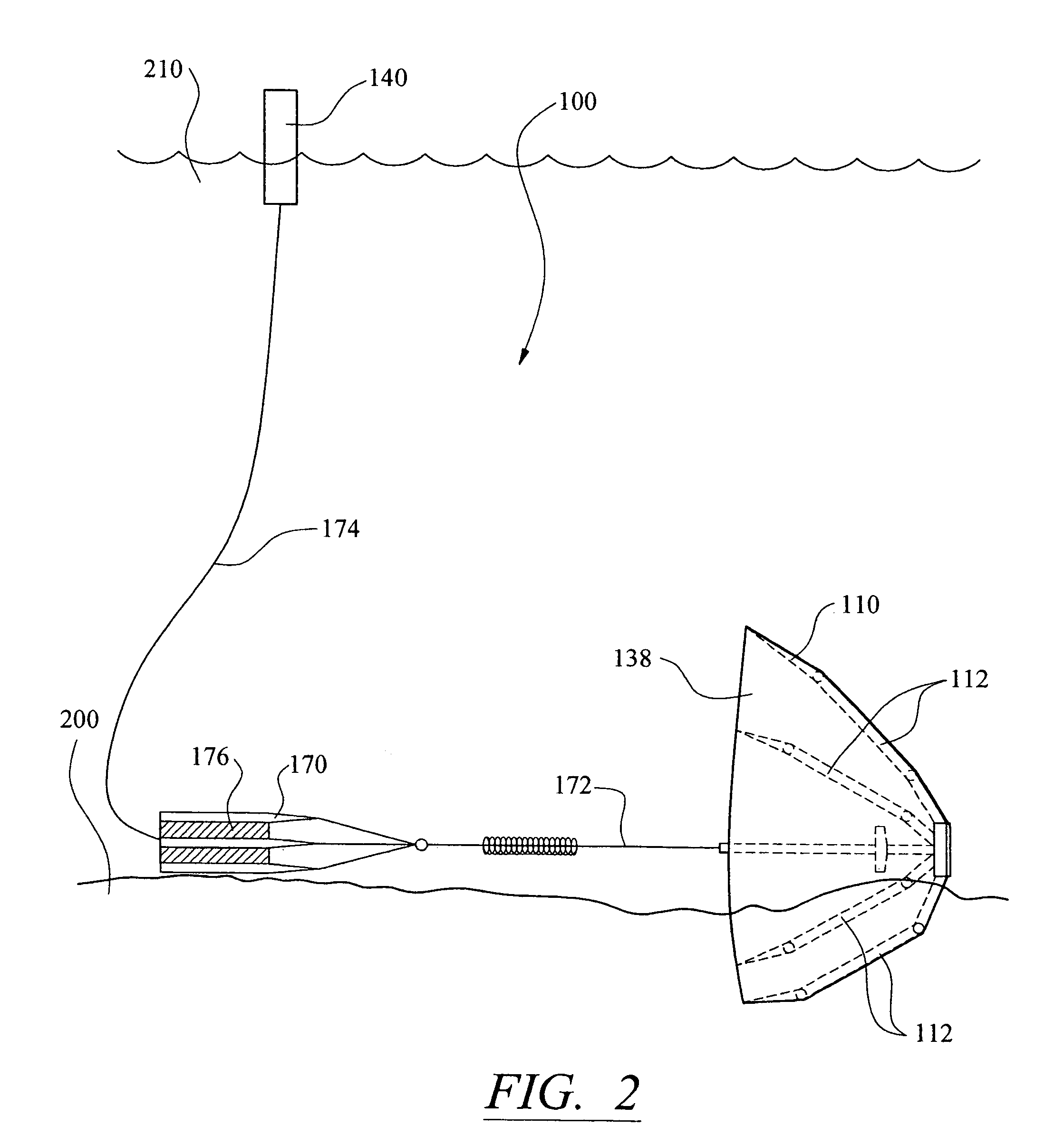
[0036]The present invention relates to a combination air brake / anchor, mooring system, and buoy packaged in a system that may be designed to conform to the “A-sized” buoy cylinder military standard, and is capable of deployment via air, water or land and / or autonomous mooring. The present invention may be designed such that it is one person portable. As such, the combined anchor, mooring module, and buoy is light enough to be carried by o...


PUM


Abstract

A self-mooring module. In particular, a self-mooring module that may be deployed by air, surface or underwater. The module includes a combination anchor/air brake, a buoy, and a mooring line. The module may also include a sensor module. The anchor, combination anchor/air brake and buoy may be used in combination as part of the module or may be used alone in different aspects. The anchor and combination anchor/air brake are foldable to conserve space. The buoy has reduced drag and increased stability versus regular buoys. The self-mooring module may also include an intelligent mooring line module that determines the amount of mooring line to be released for a particular mooring depth and does not release a substantive amount of extra or insufficient mooring line, thereby helping ensure proper placement of an sensor module. Other features include a release mechanism for releasing the anchor from the module and a mechanism for inflating the buoy.

Description

CROSS-REFERENCE TO RELATED APPLICATIONS[0001]This Application claims priority to Provisional U.S. Patent Application No. 60 / 445,309, filed Feb. 5, 2003.STATEMENT REGARDING FEDERALLY SPONSORED RESEARCH OR DEVELOPMENT[0002]This invention was made with United States government support under grant number N00014-01-1-0014 awarded by the Office of Naval Research. The United States government may have certain rights in the invention.BACKGROUND OF THE INVENTION[0003]1. Field of the Invention[0004]The present invention relates to the field of deployable systems and mooring systems, and more particularly, to the field of deployable autonomous mooring systems.[0005]2. Description of the Related Art[0006]In the last decade, interest in the ocean has shifted from the deep ocean to the littoral regions of the world. This change has been driven by the need to successfully operate in the complex littoral oceans that are characterized by intricate bottom topography, changes in water properties and t...

Claims


Application Information

Patent Timeline
IPC IPC(8): B63B22/04B63B22/18B63B22/22B63B21/24B63B21/36B63B21/48B63B22/00
CPCB63B21/243B63B21/48B63B22/18B63B22/003B63B2211/02
Inventor DRISCOLL, FREDERICK R.PANTELAKIS, THOMAS A.CASTANIER, CHRISTOPHEVENEZIA, WILLIAM A.
Owner THE UNITED STATES OF AMERICA AS REPRESENTED BY THE SECRETARY OF THE NAVY
Why Eureka
Try Eureka