Phase modulation in RF tag

a phase modulation and rf tag technology, applied in the field of radio frequency identification tags, can solve problems such as insufficient range for some applications, and achieve the effect of prolonging the communication rang

Inactive Publication Date: 2007-02-20
BATTELLE MEMORIAL INST
View PDF22 Cites 49 Cited by
  • Summary
  • Abstract
  • Description
  • Claims
  • Application Information

AI Technical Summary

Benefits of technology

[0012]An embodiment of the present invention is directed to an RF communication system that employs phase-modulated backscatter signals for RF communication from an RF tag to an interrogator. The interrogator transmits a continuous wave interrogation signal to the RF tag, which based on an information code stored in a memory, phase-modulates the interrogation signal to produce a backscatter response signal that is transmitted back to the interrogator. By employing a phase-modulated backscatter response signal rather than the amplitude-modulated backscatter response signal of prior art systems shown in FIG. 1, the RF communication system is able to reflect much more power from the interrogation signal than is possible using the prior art systems, resulting in a much longer communication range between the interrogator and RF tag.

Problems solved by technology

While this is successful for tags that are located in close proximity to an interrogator 12, for example less than three meters, this may be insufficient range for some applications, for example, which require greater than 100 meters.

Method used


Image

  • Phase modulation in RF tag
  • Phase modulation in RF tag
  • Phase modulation in RF tag

Examples


Embodiment Construction

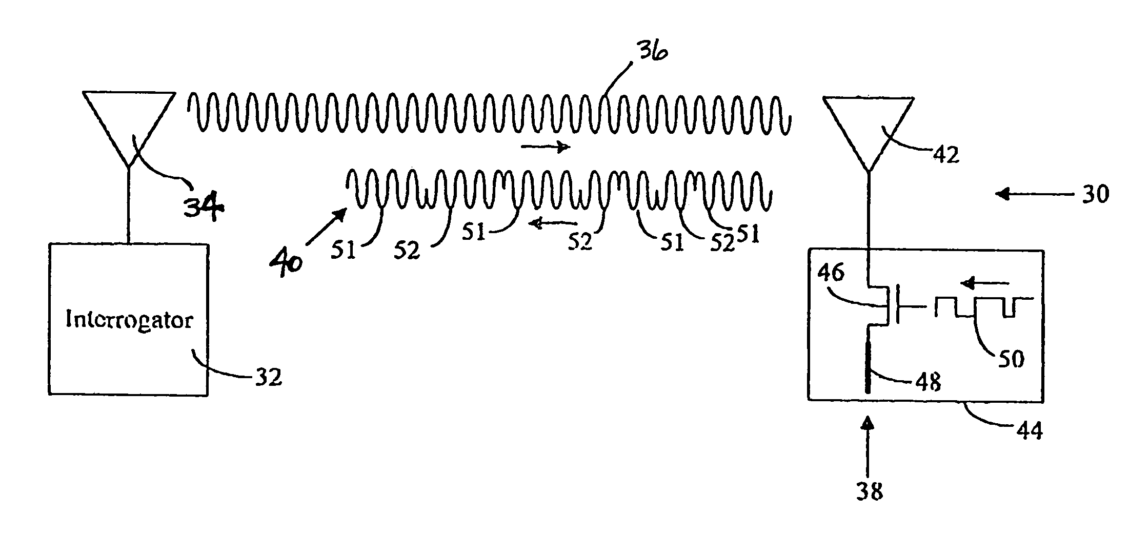
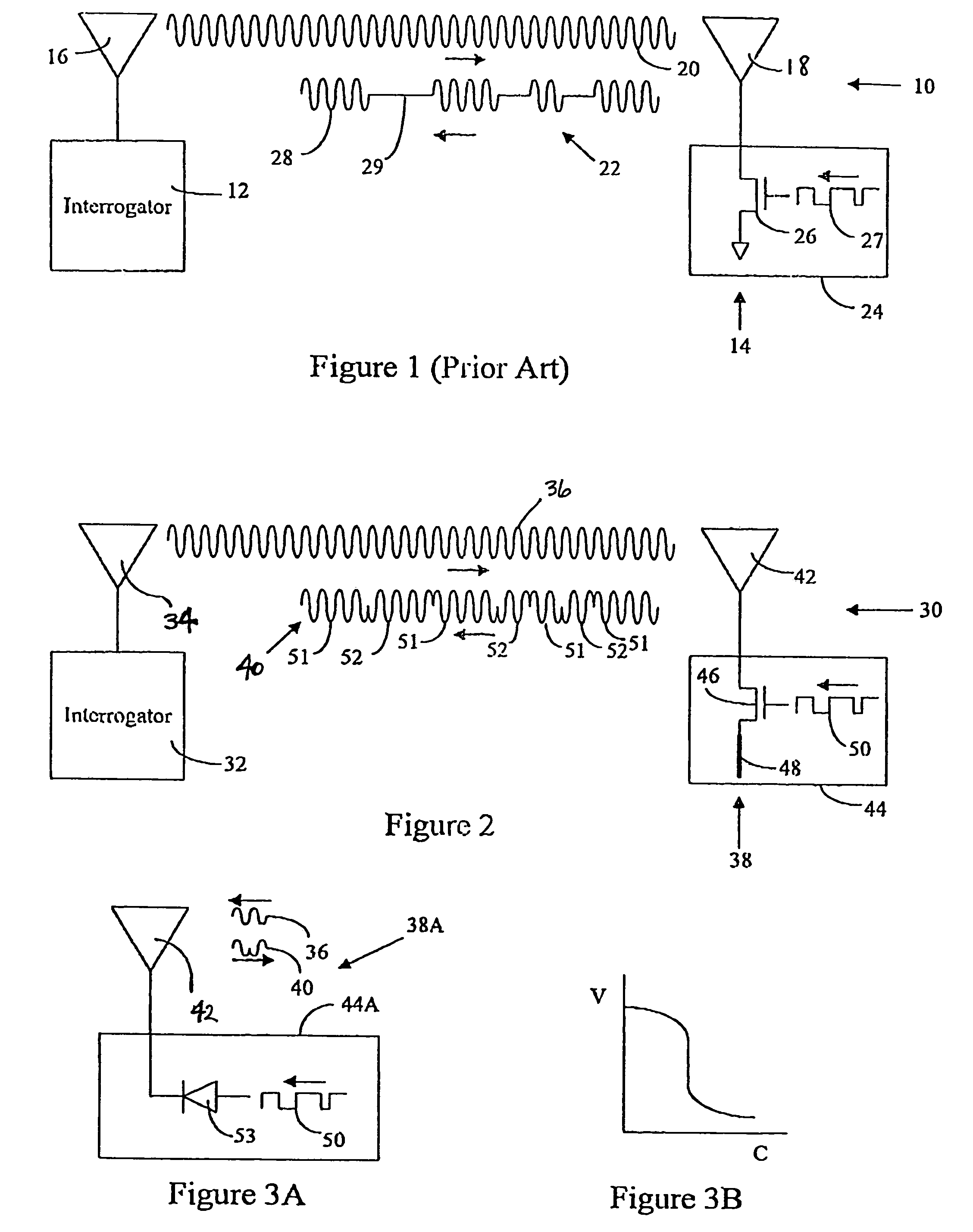
[0022]As shown in FIG. 2, an embodiment of the present invention is directed to an RF communication system 30 that employs phase-modulated backscatter signals. The RF communication system 30 includes a reader or interrogator 32 that includes an antenna 34 through which the reader transmits a continuous wave interrogation signal 36 to an RF tag 38. Based on an identification code stored in a memory (not shown) of the RF tag 38, the RF tag phase-modulates the interrogation signal 36 to produce a backscatter response signal 40 that is transmitted back to the interrogator 32.

[0023]By employing a phase-modulated backscatter response signal 40 rather than the amplitude-modulated backscatter response signal of the prior art system shown in FIG. 1, the RF communication system 30 is able to reflect much more power from the interrogation signal 36 than is possible using the prior art system of FIG. 1. That is because the RF tag 38 is always reflecting the interrogation signal 36 to produce th...


PUM


Abstract

A radio frequency (RF) communication system employs phase-modulated backscatter signals for RF communication from an RF tag to an interrogator. The interrogator transmits a continuous wave interrogation signal to the RF tag, which based on an information code stored in a memory, phase-modulates the interrogation signal to produce a backscatter response signal that is transmitted back to the interrogator. A phase modulator structure in the RF tag may include a switch coupled between an antenna and a quarter-wavelength stub; and a driver coupled between the memory and a control terminal of the switch. The driver is structured to produce a modulating signal corresponding to the information code, the modulating signal alternately opening and closing the switch to respectively decrease and increase the transmission path taken by the interrogation signal and thereby modulate the phase of the response signal. Alternatively, the phase modulator may include a diode coupled between the antenna and driver. The modulating signal from the driver modulates the capacitance of the diode, which modulates the phase of the response signal reflected by the diode and antenna.

Description

[0001]This application is a CON of Ser. No. 09 / 588,997 file Jun. 6, 2000 is abandoned.[0002]This invention was made with Government support under Contract DE-AC0676RLO1830 awarded by the U.S. Department of Energy. The Government has certain rights in the invention.FIELD OF THE INVENTION[0003]The present invention relates to radio frequency identification tags (RF tags), and in particular, to RF tags that communicate using phase modulation.BACKGROUND OF THE INVENTION[0004]Remote communication utilizing wireless equipment typically relies on radio frequency (RF) technology, which is employed in many industries. One application of RF technology is in locating, identifying, and tracking objects, such as animals, inventory, and vehicles.[0005]RF identification (RFID) tag systems have been developed that facilitate monitoring of remote objects. As shown in FIG. 1, a basic RFID system 10 includes two components: an interrogator or reader 12, and a transponder (commonly called an RF tag) 14...

Claims


Application Information

Patent Timeline
Patent Type & Authority Patents(United States)
IPC IPC(8): H04Q5/22G06K19/07
CPCG06K19/0723
Inventor CARRENDER, CURTIS LEEGILBERT, RONALD W.
Owner BATTELLE MEMORIAL INST
Why Eureka
Try Eureka