
Spark-based igniting system for internal combustion engines

a technology of internal combustion engine and spark plug, which is applied in the direction of combustion engine, machine/engine, other installations, etc., can solve the problems of requiring spark plugs, relatively expensive manufacture, and spark-ignition engines, and achieve the effect of simple and inexpensive design, construction and operation

Inactive Publication Date: 2007-02-27
MINKER GARY A
View PDF9 Cites 30 Cited by
  • Summary
  • Abstract
  • Description
  • Claims
  • Application Information

AI Technical Summary

Benefits of technology

[0016]Accordingly, it is a general object of the present invention to provide an improved spark-based igniting system for internal combustion engines which is relatively simple and inexpensive in design, construction and operation.
[0017]It is an object of the present invention to provide a spark-based igniting system for internal combustion engines which is substantially free from the production of atmospheric pollutants.
[0018]It is another object of the present invention to provide a spark-based igniting system for internal combustion engines which has an enhanced efficiency of operation.

Problems solved by technology

However, these conventional spark-ignition engines suffer from the major disadvantage of requiring spark plugs which are relatively expensive to manufacture and frequently become defective so as to need replacement.
Further, combustion in the spark-ignition engine is inefficient due to the fact that the ignition spark is applied more-or-less on a “single point” of the spark plug device and is accompanied by the production of unwanted atmospheric pollutants from the incomplete and inefficient combustion of the fuel mixture.
In addition, the petroleum-derived fuel prices have been escalating in recent years and these future supplies are unknown and no alternate fuel source will be readily available in the immediate future for replacing such petroleum-derived fuel supplies.

Method used


Image

  • Spark-based igniting system for internal combustion engines
  • Spark-based igniting system for internal combustion engines
  • Spark-based igniting system for internal combustion engines

Examples


Embodiment Construction

[0030]It is to be distinctly understood at the outset that the present invention shown in the drawings and described in detail in conjunction with the preferred embodiments is not intended to serve as a limitation upon the scope or teachings thereof, but is to be considered merely as an exemplification of the principles of the present invention.

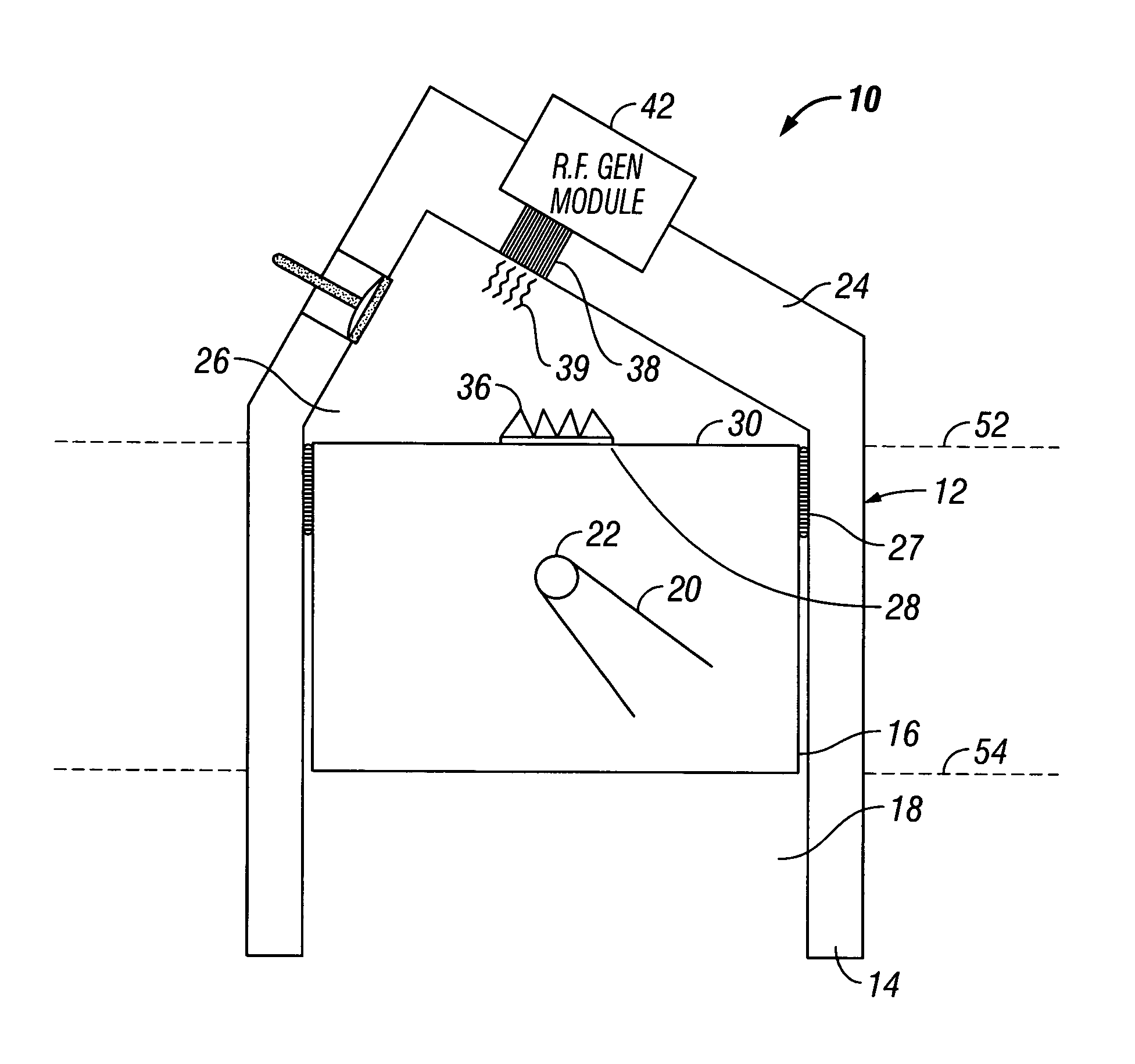
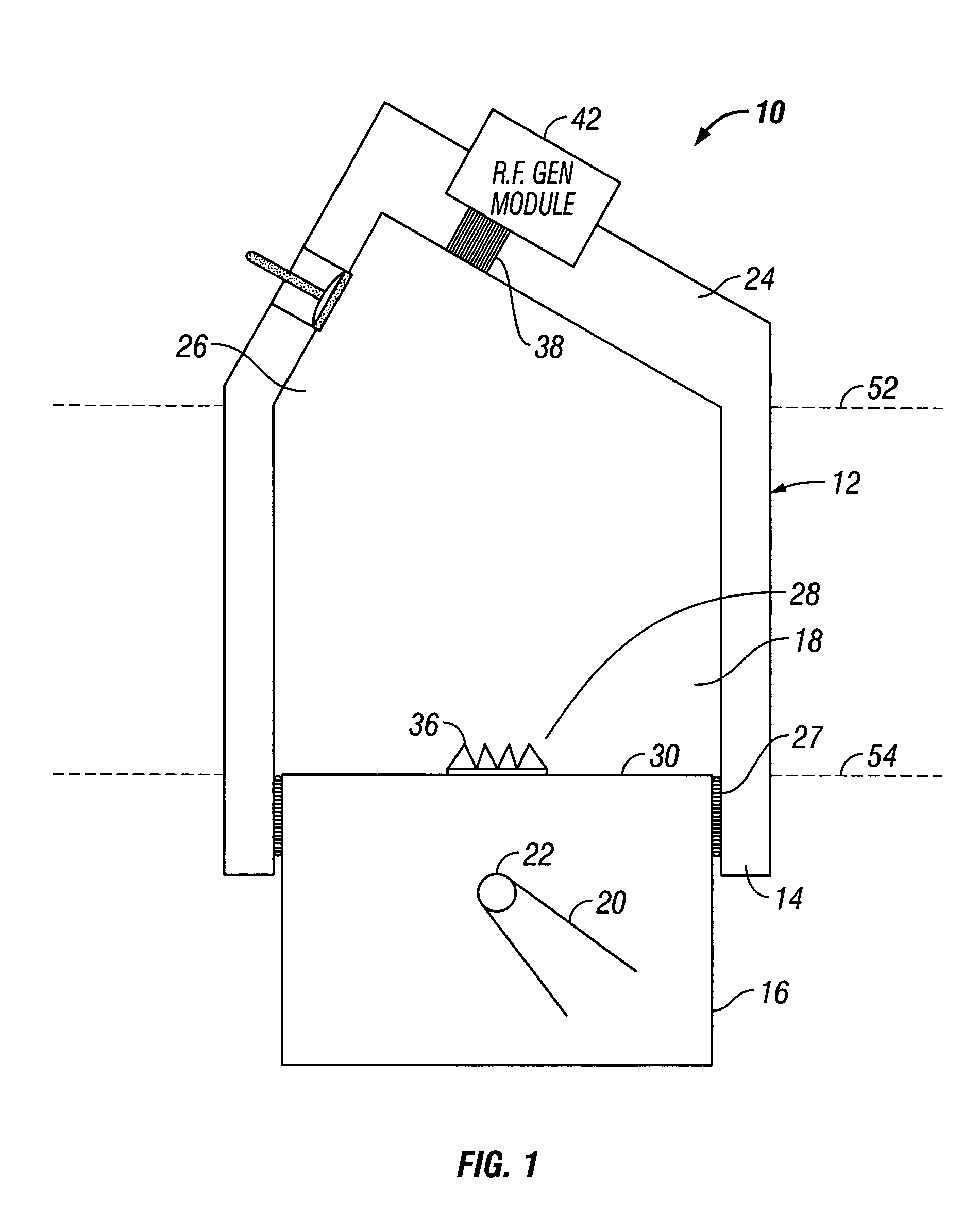
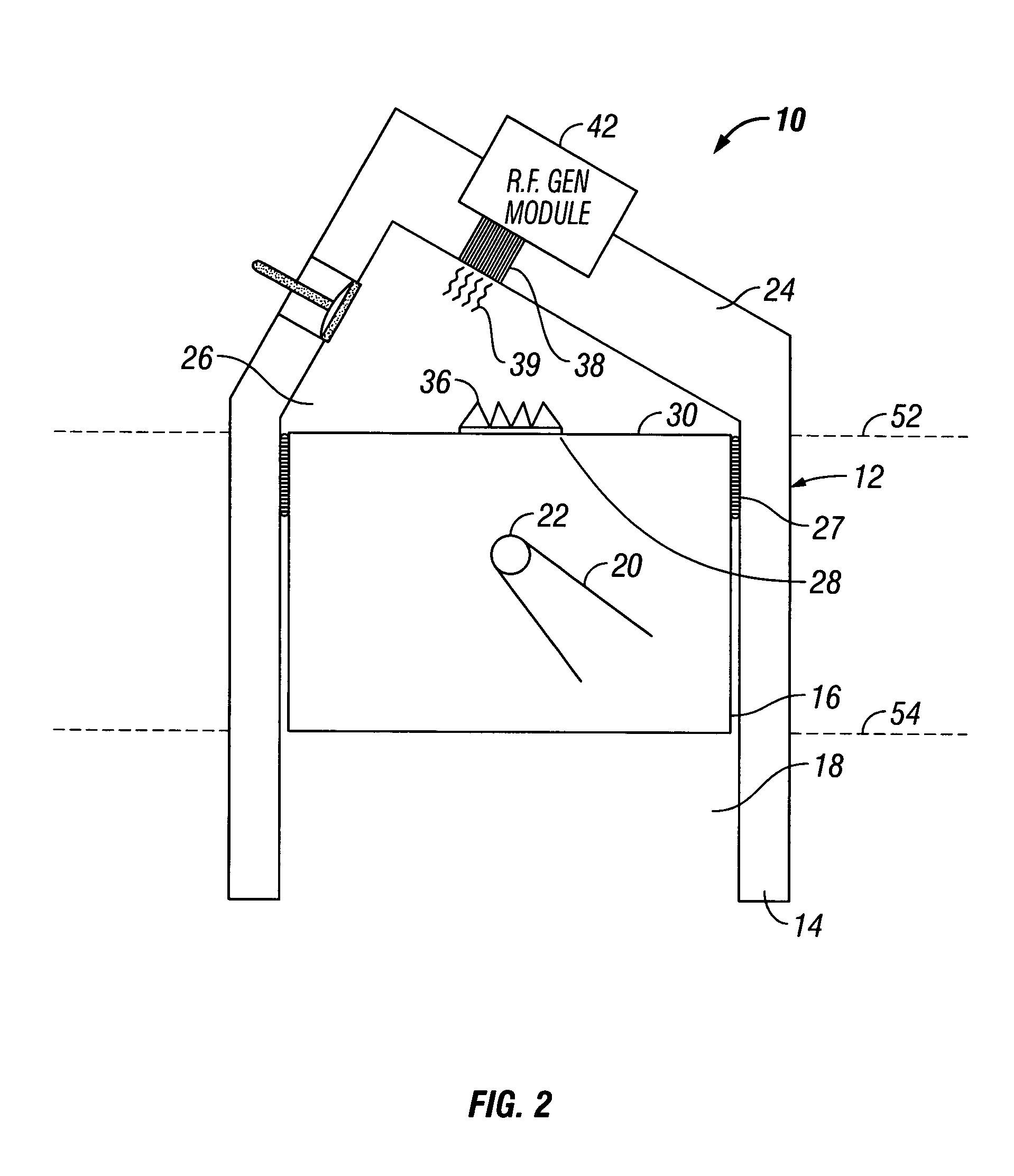
[0031]Referring now in detail to the drawings, there is illustrated in FIGS. 1 and 2 an improved spark-based igniting system 10 for an internal combustion engine 12, constructed in accordance with the principles of the present invention. FIG. 1 is a cross-sectional view of the spark-based igniting system for the internal combustion engine 12 during a compression stroke. FIG. 2 is cross-sectional view similar to FIG. 1, but with the piston at near top dead center.

[0032]The internal combustion engine 12 includes a block or cylinder assembly 14 having a plurality of pistons 16 (only one being depicted) slidably movable within a corresponding cyl...


PUM


Abstract

A spark-based igniting system for internal combustion engines includes a cylinder, at least one piston, a combustion chamber, a spark insert, and a RF energy source. The piston is disposed within the cylinder for moving slidably between a top dead center position and a bottom dead center position. The combustion chamber is formed in fluid communication with the piston. The spark insert is disposed in a top surface combustion face of the piston. The RF energy source is formed on the cylinder and adjacent to the combustion chamber for generating spark ignition energies to the spark insert to cause igniting of air / fuel mixture within the combustion chamber when the piston reaches near the top dead center position.

Description

BACKGROUND OF THE INVENTION[0001]1. Field of the Invention[0002]This invention relates generally to spark-ignition internal combustion type engines and more particularly, the present invention relates to an improved spark-based igniting system for internal combustion engines which eliminates the need of the conventional spark plug and the discharge of a high voltage into the combustion chamber.[0003]2. Description of the Prior Art[0004]As is generally well-known, spark-ignition internal combustion type engines are powered by gasoline or other petroleum-derived liquid or gaseous fuels. These combustion type engines usually utilize conventional spark plugs which are installed into the combustion chamber of the engine. The spark plugs are typically comprised of a terminal stud, insulator, shell and electrodes. The function of the spark plug is to introduce the ignition energy into the combustion chamber and to initiate the combustion of the air / fuel mixture via the electric spark produ...

Claims


Application Information

Patent Timeline
IPC IPC(8): F02P15/04
CPCF02P23/045F02P15/04
Inventor MINKER, GARY A.
Owner MINKER GARY A
Learn More