Ink jet printing apparatus

a printing apparatus and jet module technology, applied in printing and other directions, can solve the problems of reducing the operation frequency, ink droplet size, difficulty in cleaning the nozzle b, etc., and achieve the effect of reducing the mass of the jet module, enhancing printing quality, and low mass

Inactive Publication Date: 2007-02-27
JEMTEX INK JET PRINTING
View PDF13 Cites 21 Cited by
  • Summary
  • Abstract
  • Description
  • Claims
  • Application Information

AI Technical Summary

Benefits of technology

[0011]As will be described more particularly below, such a construction, wherein a T-connection rather than an F-connection is made of each jet module with the inlet and outlet manifolds, enables a significant reduction in the mass of each jet module, as well as a closer spacing between jet modules, to be made such as to enhance the printing quality.
[0017]Preferably, the two sections of the mounting device are made of a plastic material having a relatively low mass (as compared to metal). Such a construction enables the mass of the jet modules to be reduced, thereby permitting the printing to be effected with small ink droplets at relatively high frequencies for purposes of enhancing the printing quality; at the same time such a construction permits the jet modules to have a relatively large space between them if desired in order to reduce the overall cost of the printer apparatus.
[0018]According to another aspect of the present invention, there is provided an ink jet printing apparatus, comprising: a linear array of jet modules each including an inlet for receiving ink, an outlet for re-circulating the ink, a nozzle for discharging ink in the form of droplets, and a perturbation device for causing a continuous stream of ink droplets to be discharged from the respective nozzle; and an ink supply system including a a body member formed with-an inlet manifold, an outlet manifold, and a plurality of connecting passageways connecting the jet modules in parallel between the inlet and outlet manifolds; each of the nozzles being removably attached to the jet module by a coupling sleeve fixed to the body member and formed with internal threads engageable with external threads formed in the jet module to permit convenient detaching of the nozzle for cleaning purposes. The foregoing features enable each nozzle to be conveniently disassembled and cleaned as and when needed at the printing site, and thereby obviate the need for large down times or removal of the apparatus from the printing site for cleaning purposes. The foregoing features enable each nozzle to be conveniently disassembled and cleaned as and when needed at the printing site, and thereby obviate the need for large down times or removal of the apparatus from the printing site for cleaning purposes.
[0019]According to a further aspect of the present invention, there is provided ink jet printing apparatus comprising a linear array of jet modules each including an inlet for receiving ink, an outlet for re-circulating the ink, a nozzle for discharging ink in the form of droplets, and a perturbation device for causing a continuous stream of ink drops to be discharged from the respective nozzle. Each of the jet modules is equally spaced from each other in the linear array. The apparatus further comprises an ink supply system including an inlet manifold, an outlet manifold, and a plurality of connecting passageways connecting the jet modules in parallel between the inlet and outlet manifolds; and a gutter in every other space between the jet modules such that each gutter is shared by two jet modules on its opposite sides. The foregoing features not only decrease the cost of the printing apparatus but also enable the printing apparatus to be constructed more compactly, thereby enhancing printing quality.

Problems solved by technology

One drawback is that the F-connection described above of each jet module 3 with the inlet manifold 7a and outlet manifold 7b, supplying the ink to all the jet modules in parallel, results in a relatively large mass in each jet module.
This limits the operating frequency, and also the ink droplet size, of the ink jet printer.
A still further drawback in the prior art apparatus illustrated in FIGS. 1–4 is the difficulty in cleaning the nozzles 5 at the printing site without requiring major disassembly of the print head.
Thus, it was found that dirt accumulating within passageway 14 was particularly difficult to remove and significantly affected the operation of the apparatus unless it was thoroughly cleaned.
This generally required substantial down-time of the apparatus and / or removal of the apparatus for cleaning purposes.
Such an arrangement increases the size of the printer head assembly, and also the cost of its manufacture.

Method used


Image

  • Ink jet printing apparatus
  • Ink jet printing apparatus
  • Ink jet printing apparatus

Examples


Embodiment Construction

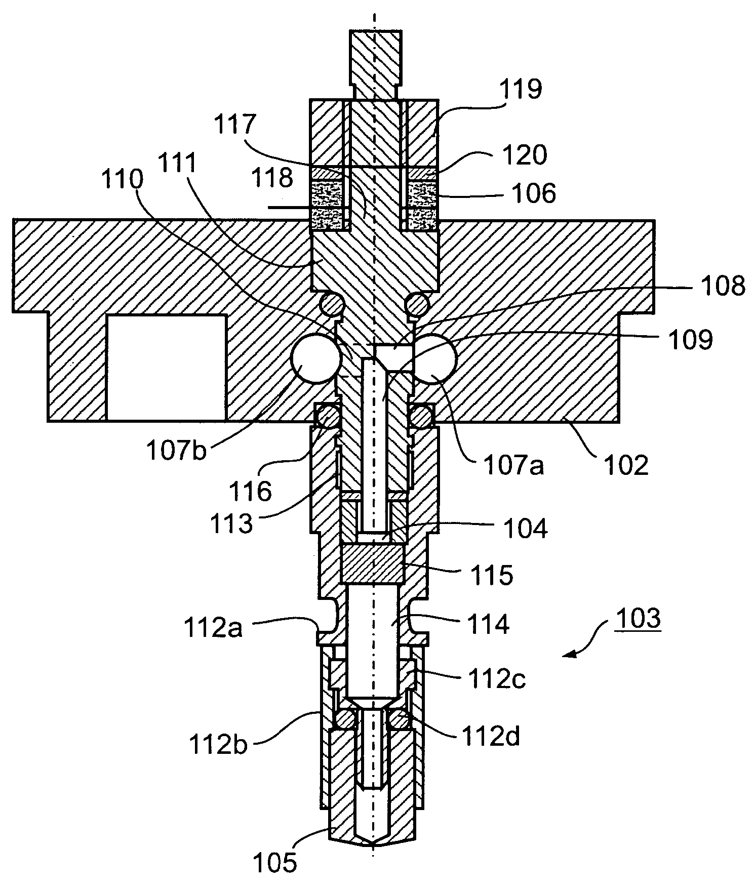
[0037]The present invention, as described below with respect to the embodiments of FIGS. 5–8, 9–12 and 13, respectively, improves the jet printing apparatus in one or more of the above respects.

The Embodiment of FIGS. 5–8

[0038]The embodiment illustrated in FIGS. 5–8 includes improvements over the prior art construction of FIGS. 1–4 in all of the above respects. To facilitate understanding the embodiment of FIGS. 5–8, the elements thereof corresponding to the prior art construction of FIGS. 1–4 will generally be identified by the same reference numerals as in FIGS. 1–4, but increased by “100”.

[0039]Thus, the apparatus illustrated in FIGS. 5–8 also includes a common mounting member 102 for mounting a linear array of jet modules 103 each including an inlet 108 (FIG. 7) for receiving ink, an outlet 110 (shown in phantom in FIG. 7) for re-circulating the ink, a nozzle 105 for discharging ink in the form of droplets, and a perturbation device in the form of a piezoelectric transducer 106 ...


PUM


Abstract

Ink jet printing apparatus includes a linear array of jet modules each having an inlet for receiving ink, an outlet for re-circulating the ink, a nozzle for discharging ink in the form of droplets, and a perturbation device for causing a continuous stream of ink droplets to be discharged from the respective nozzle. The apparatus further includes an ink supply system having an inlet manifold, an outlet manifold, and a plurality of connecting passageways connecting the jet modules in parallel between the inlet and outlet manifolds. The connecting passageways connect the inlet of each jet module to the inlet manifold and the outlet of each jet module to the outlet manifold, such as to define a T-connection of each jet module with the inlet and outlet manifolds. Such a construction reduces the mass of each jet module thereby permitting printing at higher frequencies and with smaller ink droplets.

Description

RELATED PATENT APPLICATION[0001]This application is a National Phase Application of PCT / IL02 / 01064 International Filing Date 31 Dec. 2002, which claims priority from U.S. Provisional Patent Application Ser. No. 60 / 343,587 filed 2 Jan. 2002.FIELD AND BACKGROUND OF INVENTION [0002]The present invention relates to ink jet printing apparatus of the type described in our prior U.S. Pat. Nos. 5,969,733, 6,003,980 and 6,106,107, and also in our prior International Patent Application No. PCT / IL02 / 00346 filed May 3, 2002, published on Nov. 14, 2002 as International Publication No. WO 02 / 090119 A2, the contents of which patents and application are incorporated herein by reference.[0003]Ink jet printers are based on forming droplets of liquid ink and selectively depositing the ink droplets on a substrate. The known ink jet printers generally fall into two categories: drop on-demand printers, and continuous-jet printers. Drop on-demand printers selectively form and deposit the ink jet droplets ...

Claims


Application Information

Patent Timeline
Patent Type & Authority Patents(United States)
IPC IPC(8): B41J2/175B41J2/02B41J2/17B41JB41J2/025B41J2/145B41J2/155
CPCB41J2/025B41J2/175
Inventor SHEINMAN, YEHOSHUA
Owner JEMTEX INK JET PRINTING
Why Eureka
Try Eureka