Lighting apparatus

a technology of light source and peripheral part, which is applied in the direction of lighting support devices, instruments, light source combinations, etc., can solve the problems of poor performance, difficult manufacturing of peripheral parts of lenses, and difficult lens manufacturing, and achieve the effect of maintaining the quality of outer appearan

Active Publication Date: 2007-02-27
CITIZEN ELECTRONICS CO LTD
View PDF5 Cites 38 Cited by
  • Summary
  • Abstract
  • Description
  • Claims
  • Application Information

AI Technical Summary

Benefits of technology

[0012]Therefore, a main object of the present invention is to provide a lighting apparatus in which the inside or structure of the lighting apparatus cannot be seen through it from the outside when electricity is not applied to the lighting apparatus, maintaining the quality of the outer appearance and also the light-focusing power of the lens used in the lighting apparatus.
[0013]Another object of the present invention is to provide a lighting apparatus decreasing in thickness and easier manufacturing processes of the lens having a great aperture.
[0014]Still another object of the present invention is to provide a lighting apparatus having a lot of flexibilities in a lens design used in the apparatus.
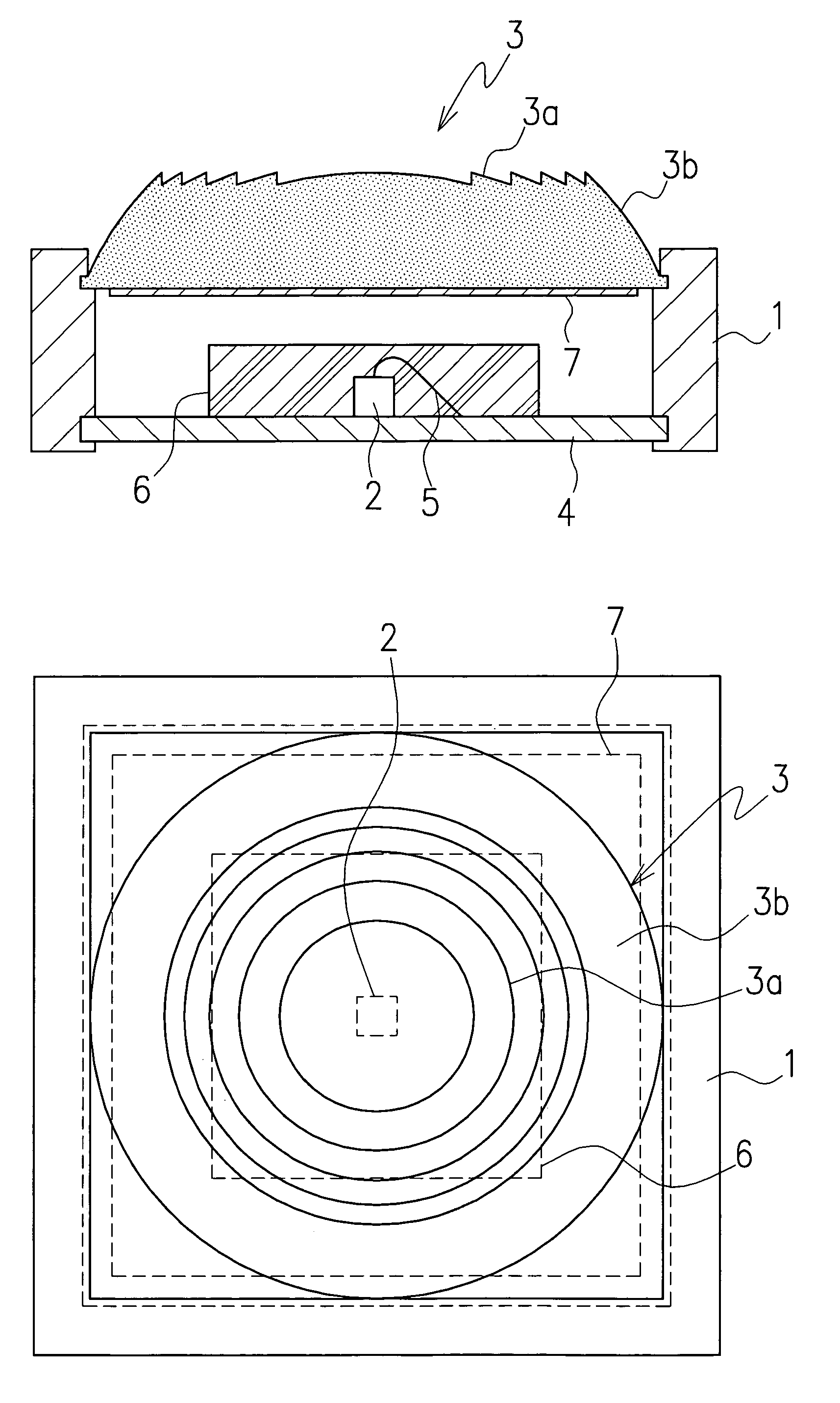
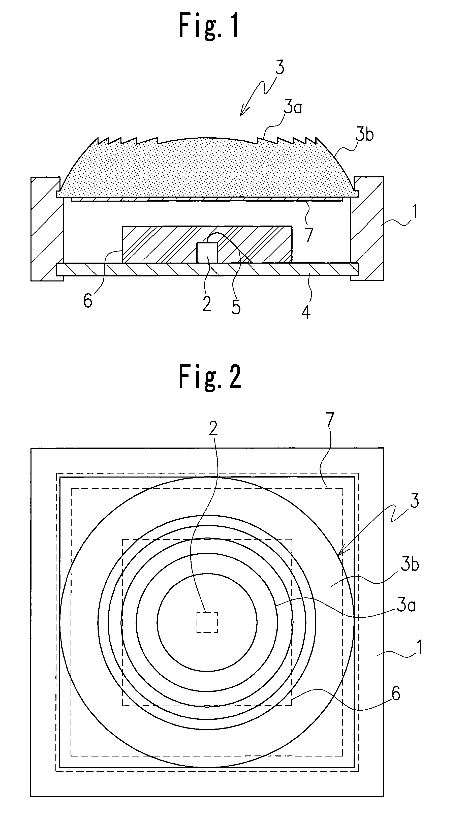
[0016]In one embodiment, the light shielding mechanism includes a half-mirror film. The light source comprises a blue-light-emitting diode encapsulated by a transparent sealing member containing YAG fluorescent material(s) and is adapted to emit white light to the outside. In another embodiment, the light source comprises a plurality of LEDs, which are adapted to emit light of same or different colors with respect to each other. The light-shielding mechanism prevents viewing of the inside of the lighting apparatus from the outside using external light when light is not being emitted from the light source.

Problems solved by technology

Accordingly, when a transparent member made of a usual resin material is formed by cutting directly or a forming die, the manufacturing of the peripheral part of the lens is very difficult.
Under such circumstances, it is difficult to manufacture a lens including a Fresnel lens surface having a large aperture prefer to collect light, in which a ratio of an outer diameter to a focal distance in the lens is larger and the inclined surface of each prismatic portion at the peripheral part is sharp, the performance also has no advantage over the usual lens.
This results in damage of an exterior appearance of the lighting apparatus.
However, because the emitted light from the LED 41 is also scattered in the structure, even if a light-focusing lens is used, it is not possible to collect light, or the lighting apparatus becomes incomplete.

Method used


Image

  • Lighting apparatus
  • Lighting apparatus
  • Lighting apparatus

Examples


second embodiment

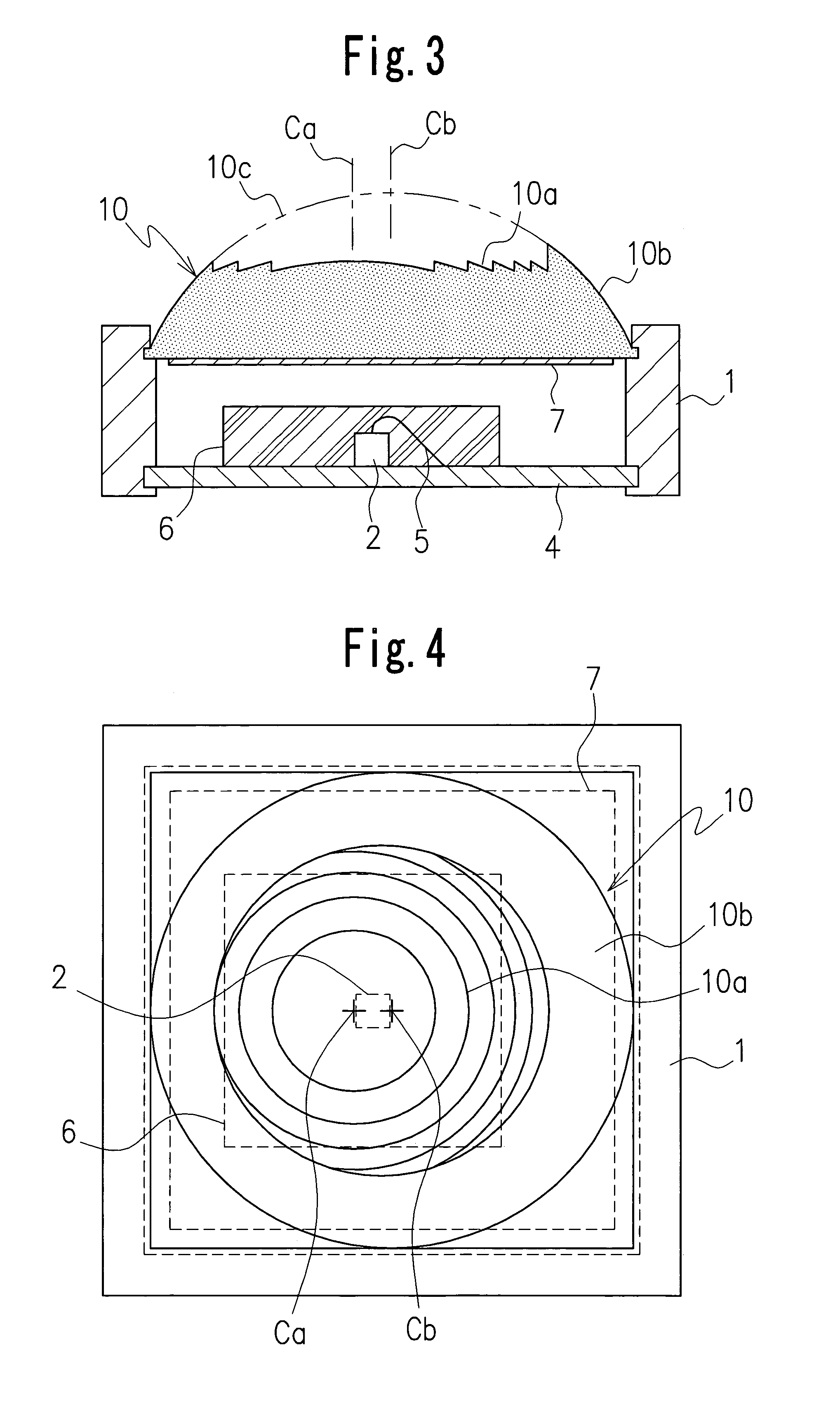
[0037]FIGS. 3 and 4 illustrate the lighting apparatus according to the present invention.

[0038]The lighting apparatus in the second embodiment is the same as the first embodiment in the basic structure and the operation, but it includes a lens 10 having a structure slightly different from that of the lens 3. The lens 10 has a Fresnel lens surface 10a provided on a central part of the lens and a smoothed lens surface 10b provided on a peripheral part of the lens, similarly as the lens 3. However, the lens 10 differs from the lens 3 in that a central axis or optical axis Ca of the Fresnel lens surface 10a deviates slightly from a central axis or optical axis Cb of the lens surface 10b corresponding to a portion of a virtual lens surface 10c. In addition, a central axis of an emission surface of the light source or LED deviates from the central axes Ca and Cb of the Fresnel lens surface 10a and the lens surface 10b. Alternatively, the central axis of the emission surface may be arrange...

third embodiment

[0040]FIGS. 5 and 6 illustrate the lighting apparatus according to the present invention.

[0041]A plurality of lighting mechanisms 20, which are arranged in a planar state, are used in the embodiment. Each of the lighting mechanisms 20 has a structure similar to the lighting apparatus in the first embodiment as shown in FIG. 1. The number of the lighting mechanisms is optionally determined. Lenses 21 in each of the plurality of lighting mechanisms 20 are formed integrally with respect to each other to form a lens assembly. The lens assembly is supported on the support 22. Each lens 21 has a Fresnel lens surface 20a and a lens surface 20b, similarly to the lens 3. A half-mirror film 23 is provided on a lower surface of the lens assembly of the lenses 21 throughout the whole of the lower surface. A lower surface of each of the lenses 21 forms a plane which faces chip-like LEDs, as light sources. These LEDs 24 are mounted on a larger substrate 25. In addition, the LEDs 24 are encapsulat...

fourth embodiment

[0043]FIGS. 7 and 8 illustrate the lighting apparatus according to the present invention.

[0044]In the lighting apparatus shown in the embodiment, a plurality of LEDs 31R, 31G and 31B are disposed below one lens 30. The lens 30 has a Fresnel lens surface 30a and a lens surface 30b. In order to form mixed illumination light with three original colors of red, green and blue, for example, the LEDs 31R, 31G and 31B each emitting original color light are disposed close to each other and mounted on a substrate 32 (see FIG. 8). A half-mirror film 33 is provided on a lower surface of the lens 30. Meanwhile, a conical or pyramidal reflecting surface 35 may be provided on the support 34 in the lighting apparatus in order to employ light-emission in all directions effectively. A surface treatment increasing a reflection coefficient is provided on the reflecting surface 35.

[0045]In the embodiment, a structure in which the sealing member 36 for sealing the LEDs 31R, 31G and 31B does not include t...


PUM

PropertyMeasurementUnit
reflectanceaaaaaaaaaa
metallicaaaaaaaaaa
colorsaaaaaaaaaa

Abstract

A lighting apparatus comprising a support, a light source having an emission surface and disposed in the support, a lens disposed to face the emission surface of the light source, and a half-mirror film provided on at least a surface of the lens, the half-mirror film being a thin film comprising a metallic material such as aluminum, the lens being a light-focusing lens, the lens having a peripheral part and a central part, the peripheral part including a lens surface comprising a smoothly curved surface, and the central part including a Fresnel lens surface.

Description

CROSS-REFERENCE TO THE RELATED APPLICATION[0001]The application claims the priority benefit of Japanese Patent Application No. 2004-68167, filed on Mar. 10, 2004, the entire descriptions of which are incorporated herein by reference.BACKGROUND OF THE INVENTION[0002]1. Field of the Invention[0003]The present invention relates to a lighting apparatus in which light source(s) such as LED(s) and a light-focusing lens are combined.[0004]2. Related Art Statement[0005]Conventionally, many of lighting apparatuses used for reading and writing CDs, DVDs or used as a backlight system in various optical applications include a support, a light source such as an LED, lamp or the like attached to the support, a lens attached to or formed integrally with the support to face the light source, and are configured to illuminate brightly a predetermined object or scope so as to have a predetermined property to focus light emitted from the LED and so on.[0006]FIG. 9 illustrates a first conventional light...

Claims


Application Information

Patent Timeline
Patent Type & Authority Patents(United States)
IPC IPC(8): F21V5/00F21V5/04F21S2/00F21V7/22F21Y101/02G02B3/08G02F1/13357
CPCF21V5/007F21V5/045G02B3/08H01L33/58F21K9/00F21V13/04H01L33/60F21Y2113/007G02F1/133603F21Y2101/02F21Y2113/17F21Y2115/10H01L2224/48091H01L2924/181H01L2924/00014H01L2924/00012
Inventor SHIMURA, TAKASHI
Owner CITIZEN ELECTRONICS CO LTD
Why Eureka
Try Eureka