

Method of operating a wind turbine
a wind turbine and wind power technology, applied in the direction of rotors, vessels, marine propulsion, etc., can solve the problems of reducing the effect of the wind turbine, imbalance in the rotor, and particularly high risk of ice formation, so as to reduce the wear of mechanical parts, quick and easy switch, and reduce the effect of mechanical wear
- Summary
- Abstract
- Description
- Claims
- Application Information
AI Technical Summary
Benefits of technology
Problems solved by technology
Method used
Image

Examples
Embodiment Construction
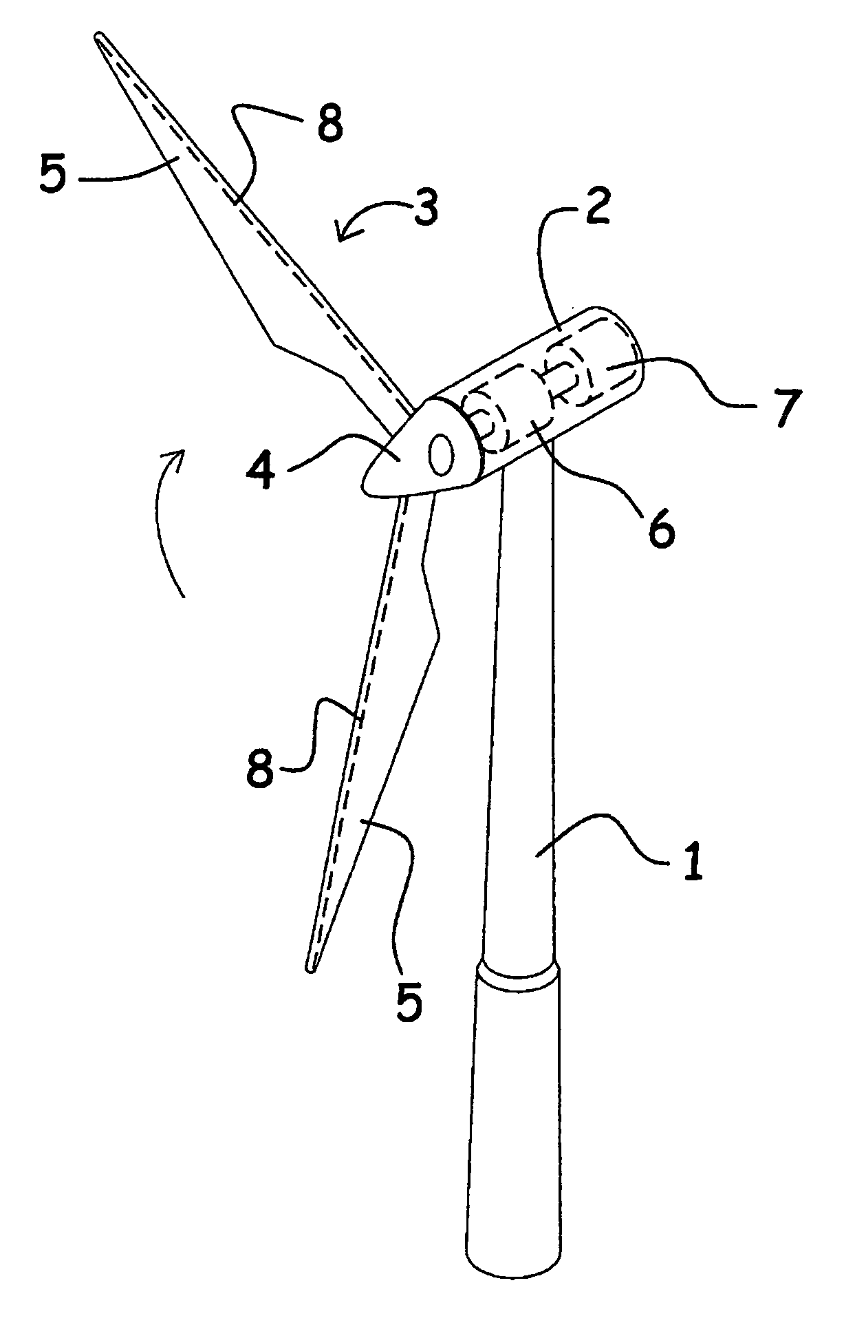
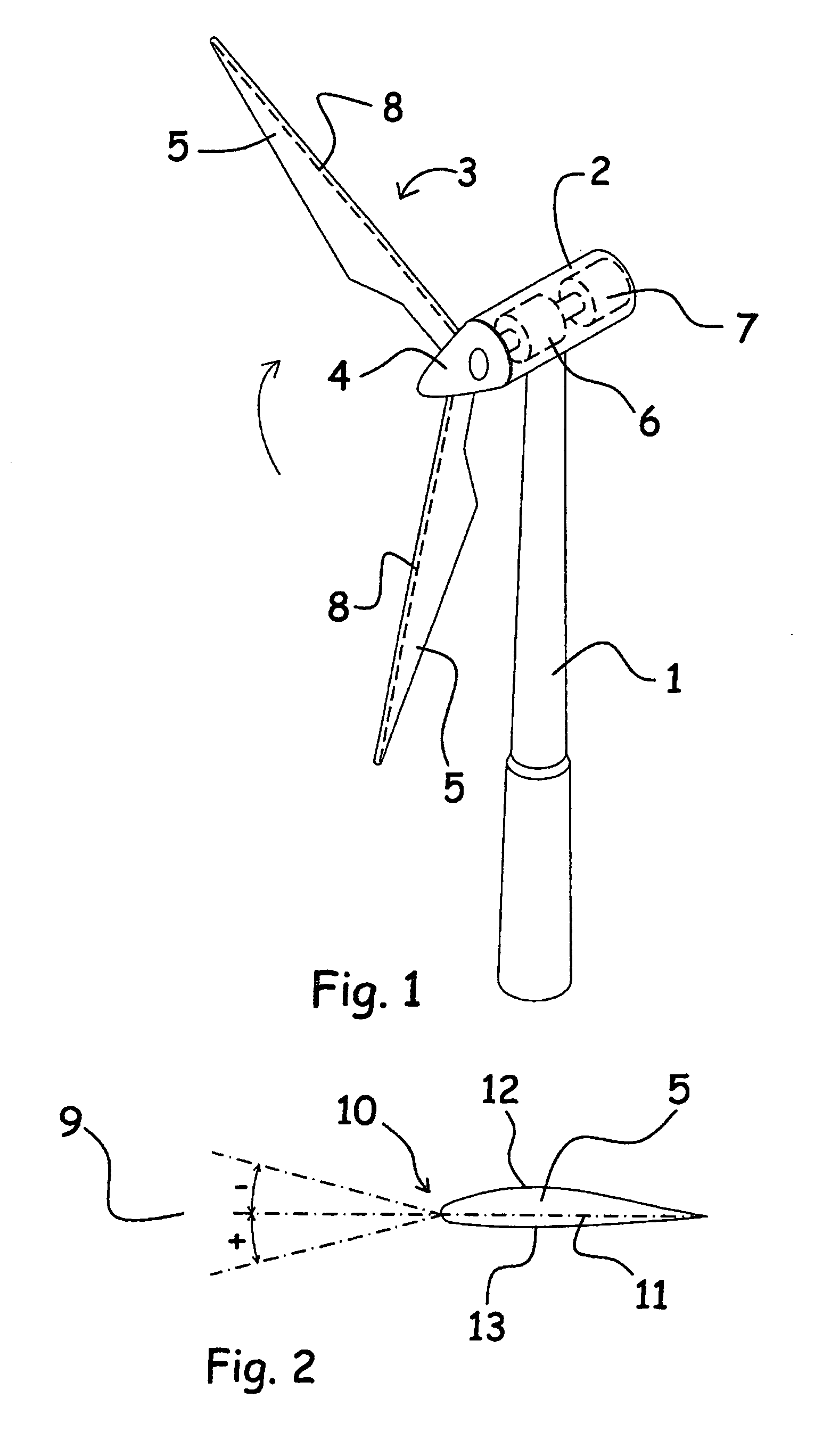
[0012]The object of the invention is to provide a method of controlling on which areas of a wind turbine blade icing occurs under certain climatic conditions and at the same time to prevent icing in other areas of a wind turbine blade. A particular object is to provide a method of operating a wind turbine blade, whereby icing is limited to the leading edge area of the blade. It is further the object of the invention to provide a method, whereby a more operational wind turbine blade is obtained in climatic conditions, where there is a risk of icing on the turbine blade, and at weak wind.
[0013]The method according to the invention is characterised in that in climatic conditions, where there is a risk of icing on the blades, and no or weak wind, the generator is used as a motor for the rotor, the rotational speed and pitch angle of the blades being adjusted such that icing occurs in areas of the blades, in particular in the leading edge area of the blades, where an ice abatement means ...
PUM
 Abstract
Description
Claims
Application Information