Apparatus and method for measuring jaw motion

a technology of jaw motion and apparatus, applied in the field of apparatus for measuring jaw motion, can solve the problems of long measuring time of hand-operated apparatus, unreliable degree of reproducibility, and conflict between patients and doctors, and achieve excellent reproducibility, shortening the period of measuring time, and applicability to cad technology

Active Publication Date: 2007-02-27
KOREA INST OF SCI & TECH
View PDF12 Cites 21 Cited by
  • Summary
  • Abstract
  • Description
  • Claims
  • Application Information

AI Technical Summary

Benefits of technology

[0009]The present invention was devised to solve above the problems of the prior art, and has the purpose of producing a appropriate apparatus for measuring the jaw motion which has a shortened period of measuring time, excellent degree of reproducibility, and applicability to CAD technology.
[0010]The other object of present invention is to provide a jaw motion measuring apparatus that can directly mark the center of the motion of jaw, thus being applicable to the conventional diagnosis of occlusion and dental treatment using occlusion device and plaster.
[0013]The fixed marker has the shape of plate and a borderline with a specific color is provided at the edge of the fixed marker for the easy discrimination from the surroundings. The fixed marker has a corner point extraction marker formed on the borderline for the extraction of corner point which is needed to establish the fixed marker local coordinate system, and the corner point extraction marker has a different color from the borderline. Plurality of quadrangles are arrayed in a checkered pattern inside the borderline which is formed on the surface of the fixed marker, and the corner point is identified as the point where corners of quadrangles meet each other.
[0015]The coupling device is comprised of: a cross bar, a holding fixture, one end of which is anchored on the lower jaw of patient and the other end of which is connected to the mid-point of the cross bar in a manner that the other end of the holding fixture can make rotational movement in relation to the cross bar; a pair of translation frames connected to the both end of the cross bar in a manner that the translation frame can make translational and rotational movement in relation to the cross bar; and a measuring frame, one end of which is connected to the translation frame in a manner that the measuring frame can make a straight motion in the direction of orthogonal to the cross bar, and the other end of which is connected to the movable marker. The movable marker is removably connected to the other end of the measuring frame.
[0018]The orbital plane marker has the shape of thin plate, and a borderline with a specific color is provided at the edge of the orbital plane marker for the easy discrimination from the surroundings. Four quadrangles are arrayed in a checkered pattern inside the borderline that is formed on the surface of the orbital plane marker, and the corner point of the orbital plane marker is identified as the point where corners of four quadrangles meet each other.

Problems solved by technology

But, this hand-operated apparatus has defects of long measuring time, which conflicts both patients and doctor all together, and the degree of reproducibility was unreliable.
In addition, hand-operated apparatus is incapable of producing the adequate data for the diagnosis and treatment of jaw occlusion using CAD, which is in under condense research.
But it is pretty expensive than the hand-operated apparatus, and has difficulties in defining the orbital plane, which is a important concept in the construction of prosthetic devices.
Meanwhile, the measuring apparatus using cameras are under research, most of which are based on the Stereo Vision Processing technology employing marker, but was not commercialized yet.
U.S. Pat. No. 4,836,778 and U.S. Pat. No. 5,340,390 disclose the apparatus using camera, but those inventions made no reference to the substantial dental occlusion and treatment, thus lacking practicality.
Especially, dental occlusion simulation system, which uses CAD technology, is under dynamic research, and such simulation system requires low-priced and automated jaw motion measuring apparatus.

Method used


Image

  • Apparatus and method for measuring jaw motion
  • Apparatus and method for measuring jaw motion
  • Apparatus and method for measuring jaw motion

Examples


Embodiment Construction

[0036]Hereinafter, the preferred embodiment of the present invention will be described in greater detail with reference to the accompanying drawings.

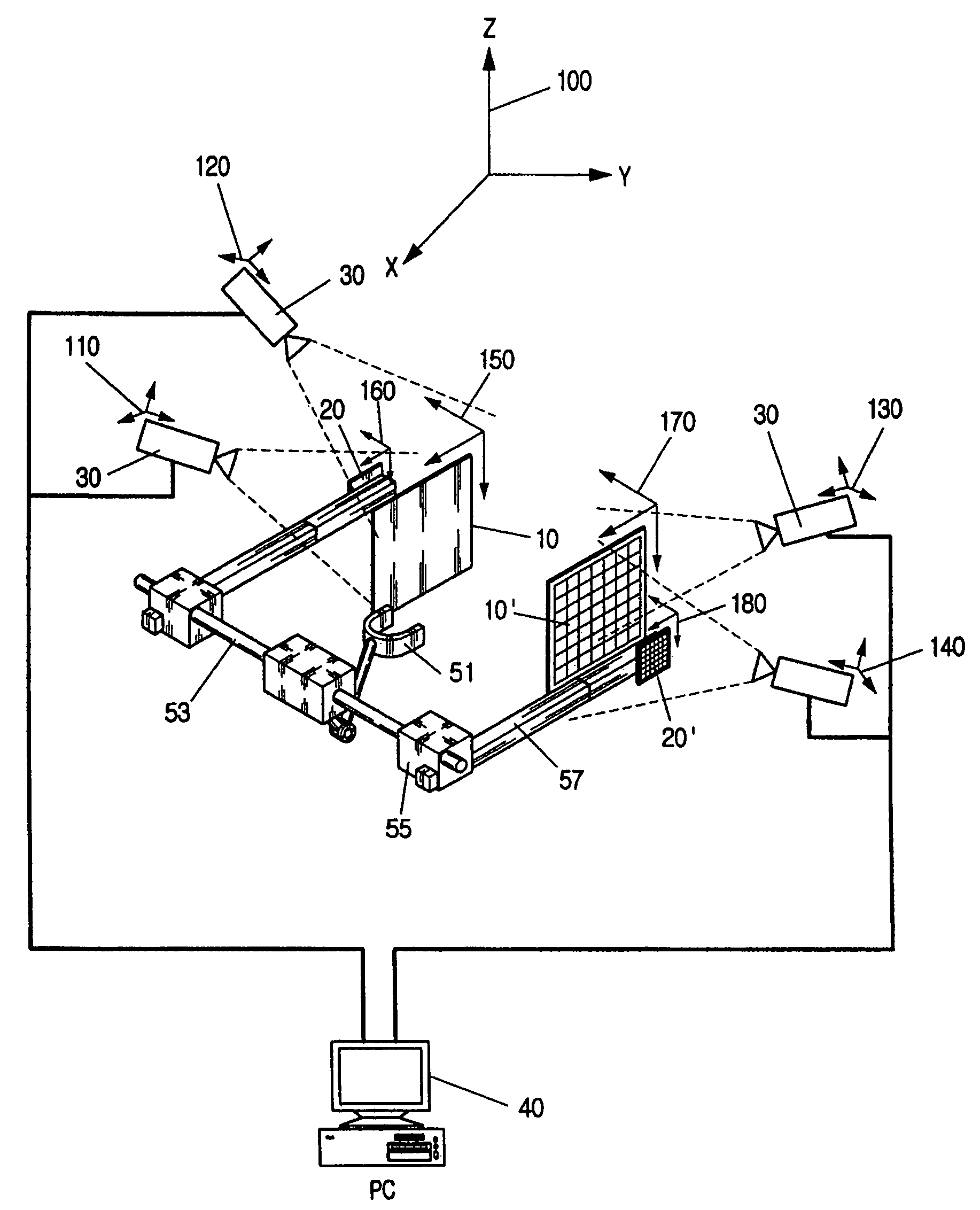
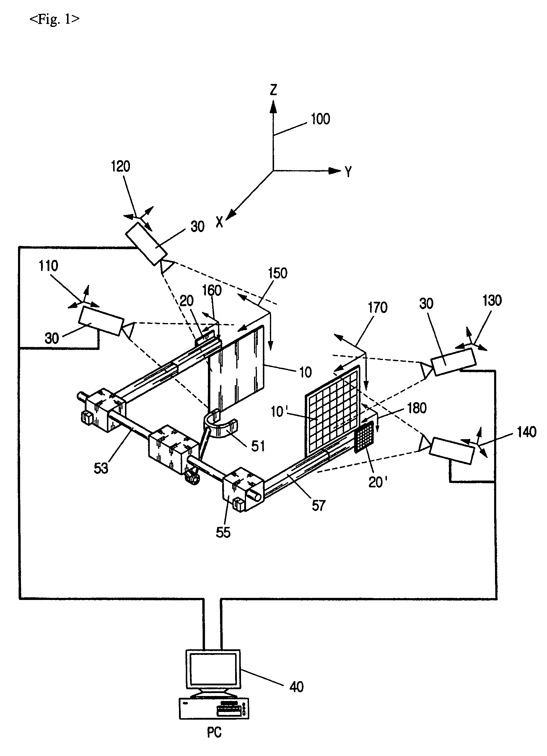
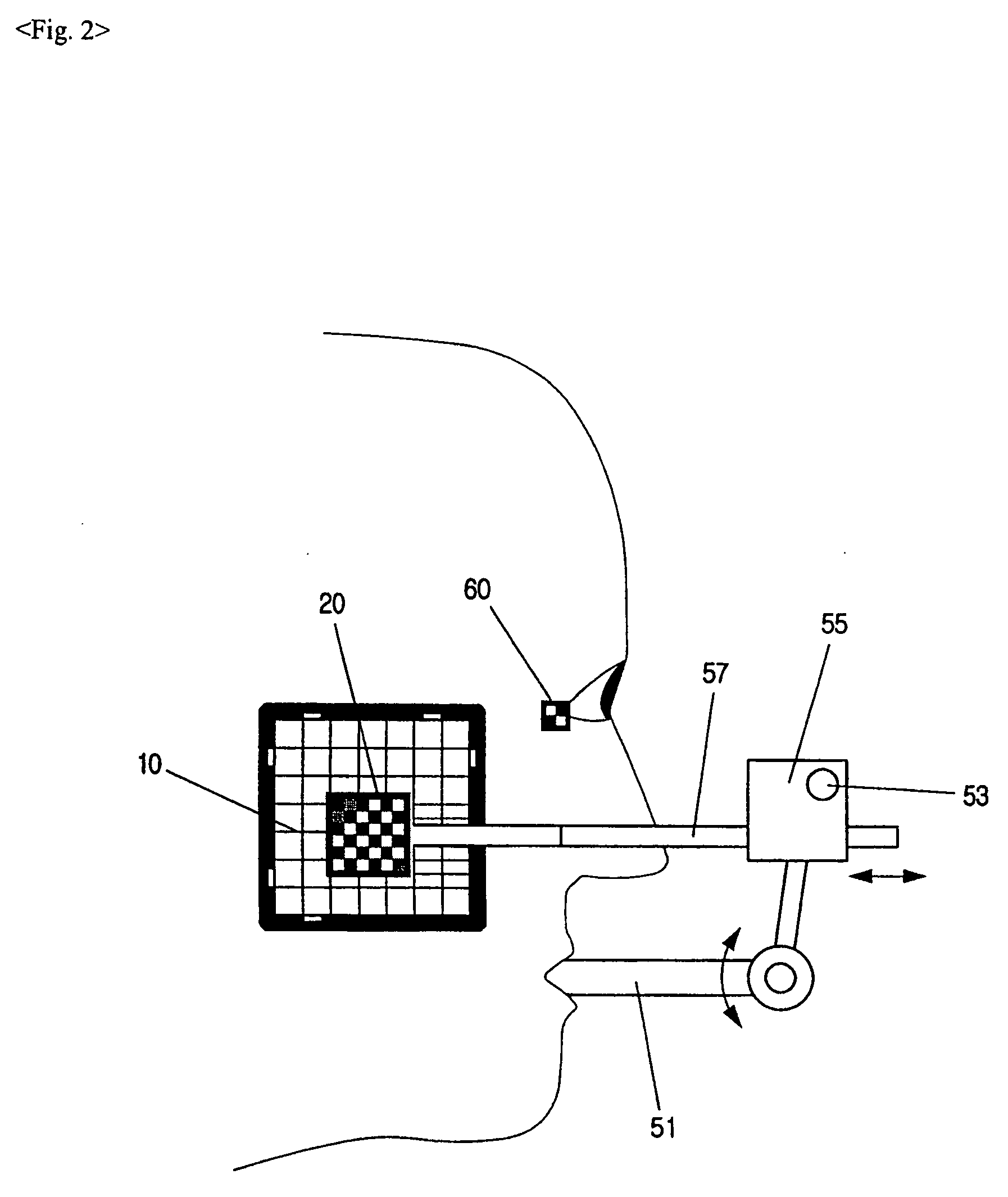
[0037]FIG. 1 is a schematic view of jaw motion measuring apparatus of the present invention.

[0038]As illustrated in FIG. 1, jaw motion measuring apparatus according to present invention comprises a pair of fixed marker 10, 10′ attached to both sides of face of patient; two movable marker 20, 20′ disposed to face the fixed marker in a spaced distance and to move in unison with the movement of the lower jaw of patient; four cameras 30 recording the relative movement of the movable marker in relation to the fixed marker, as lower jaw moves; and personal computer 40 for receiving and processing the image signals fed from connected cameras.

[0039]Movable marker 20, 20′ is connected to holding fixture mounted on the lower jaw of patient, through cross bar 53, translation frame 55 and measuring frame 57 so as to move in unison with the movement...


PUM


Abstract

An apparatus for measuring jaw motion has a pair of fixed marker attached to both sides of face of patient, a pair of movable markers disposed to face the fixed marker in a spaced distance and to move in unison with the movement of the lower jaw of patient, four cameras recording the three-dimensional movement of the movable marker relative to the fixed marker, as lower jaw moves, and personal computer for receiving and processing the image signals fed from connected cameras. The apparatus can accurately measure the location of the center of patient's jaw motion and the moving track thereof with stereo vision processing of the image signals obtained from camera.

Description

CROSS-REFERENCE TO RELATED APPLICATIONS[0001]This application claims the benefit of Korean Patent Application No. 2002-50544, filed on Aug. 26, 2003, in the Korean Intellectual Property Office, the disclosure of which is incorporated herein by reference.BACKGROUND OF THE INVENTION[0002]1. Field of the Invention[0003]The present invention relates to an apparatus for measuring the motion of jaw for the diagnosis of dental occlusion, and more practically, it relates to a jaw motion measuring apparatus which is short in measuring time and good at the degree of reproducibility.[0004]2. Description of the Prior Art[0005]The analysis of jaw motion is a fundamental element in the field of reconstruction of jaw occlusion and dental treatment of jaw or teeth. In this field, hand-operated apparatus was used to measure the motion of jaw and to analyze and reproduce it. But, this hand-operated apparatus has defects of long measuring time, which conflicts both patients and doctor all together, an...

Claims


Application Information

Patent Timeline
Patent Type & Authority Patents(United States)
IPC IPC(8): A61B5/103A61B5/117G01B11/00A61B5/11A61C19/045
CPCA61C19/045A61B5/11
Inventor KIM, MUN-SANGKIM, JOONG-HAN
Owner KOREA INST OF SCI & TECH
Why Eureka
Try Eureka