
AC winding with integrated cooling system and method for making the same

a technology of ac winding and integrated cooling system, which is applied in the direction of windings, magnetic circuit rotating parts, magnetic circuit shape/form/construction, etc., can solve the problems of insufficient or practical known cooling techniques, negative affecting capacity and efficiency of electric machines, and ac losses dominating the operation of electric machines. cost

Inactive Publication Date: 2007-02-27
GENERAL ELECTRIC CO
View PDF7 Cites 16 Cited by
  • Summary
  • Abstract
  • Description
  • Claims
  • Application Information

AI Technical Summary

Benefits of technology

"The patent text describes an AC winding for an electric machine that includes a series of serially connected AC bars. Each AC bar has a series of turns formed by litz wire with a plurality of strands and a cooling tube. The individual strands are positioned adjacent to the cooling tube at transfer points to facilitate heat transfer. The winding also includes a phase to ground insulation for providing electrical phase to ground insulation for the AC bar. The method of manufacturing the AC winding involves winding the litz wire into a coil, insulating it with a thermally activated adhesive, shaping it into a predetermined shape, and heating it for curing the adhesive. The technical effects of this patent text include improved heat transfer and more efficient cooling of the electric machine, which leads to improved performance and reliability."

Problems solved by technology

The occurrence of AC losses in armature windings is also known to negatively affect capacity and efficiency of electric machines.
In high frequency machines used for applications calling for high speed and / or high power density, such as machines operating at frequencies significantly higher than 60 Hz, the AC losses can dominate operation of the electric machine.
Furthermore, the heat generation escalates such that known cooling techniques are not sufficient or practical.
For example, the cooling method using hollow conductors becomes impractical, as the conductors in high frequency machines are typically numerous, thin, and not conducive to having an interior channel.

Method used


Image

  • AC winding with integrated cooling system and method for making the same
  • AC winding with integrated cooling system and method for making the same
  • AC winding with integrated cooling system and method for making the same

Examples


Embodiment Construction

[0018]Embodiments of the present disclosure will be described herein below with reference to the accompanying drawings. In the following description, well-known functions or constructions are not described in detail to avoid obscuring the invention with unnecessary detail. Throughout the figures, like reference numerals represent like elements.

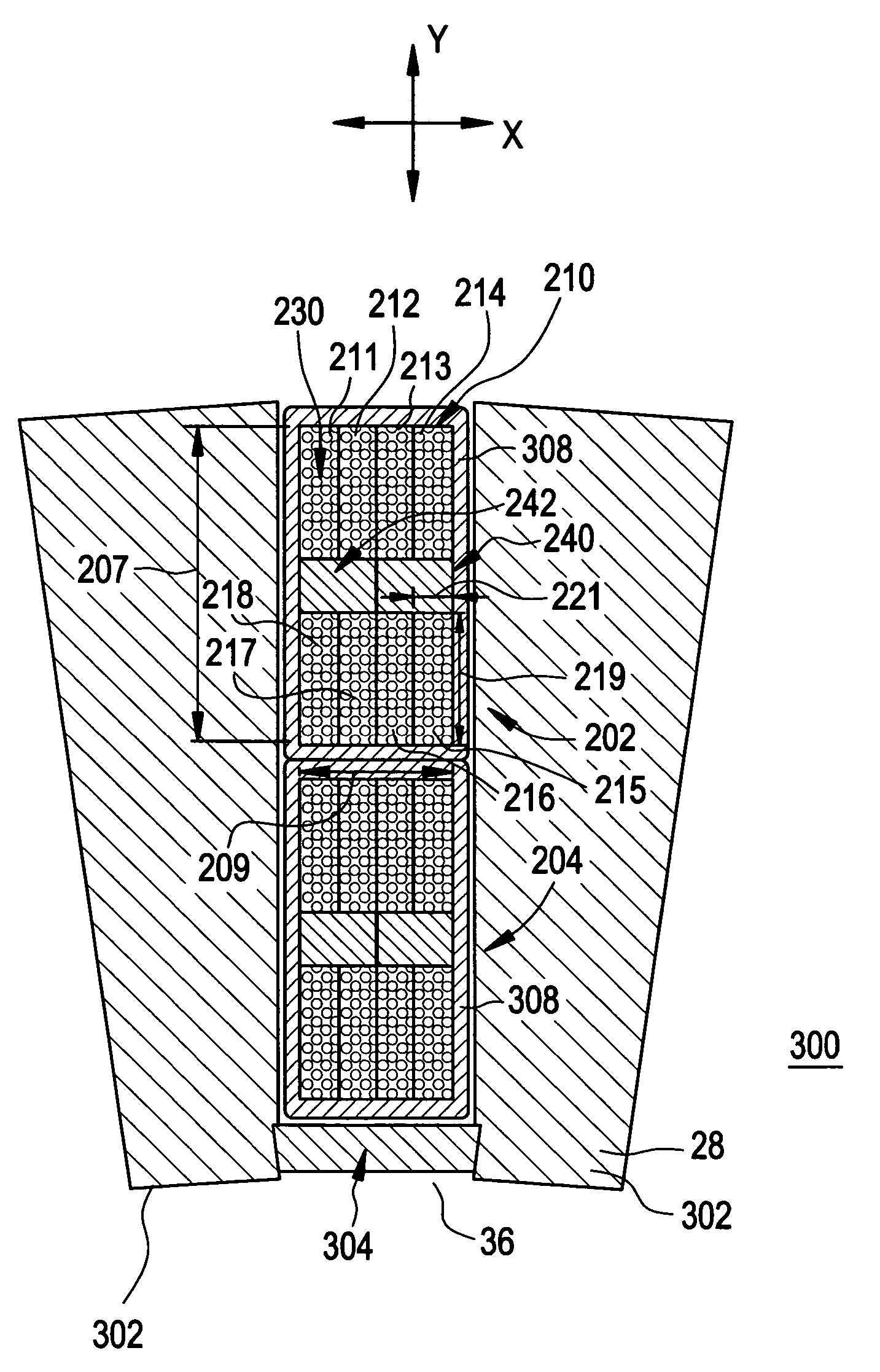
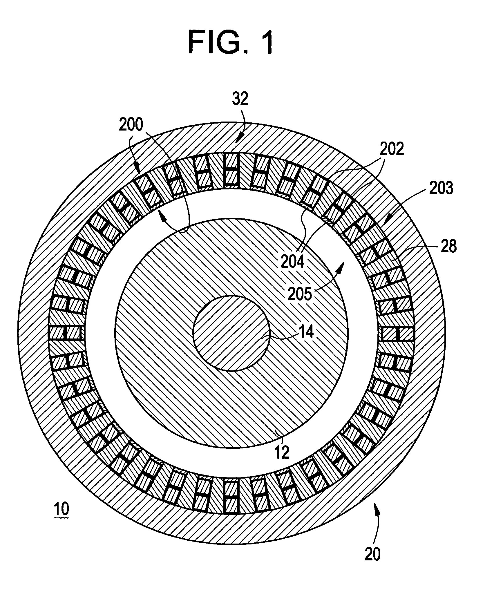
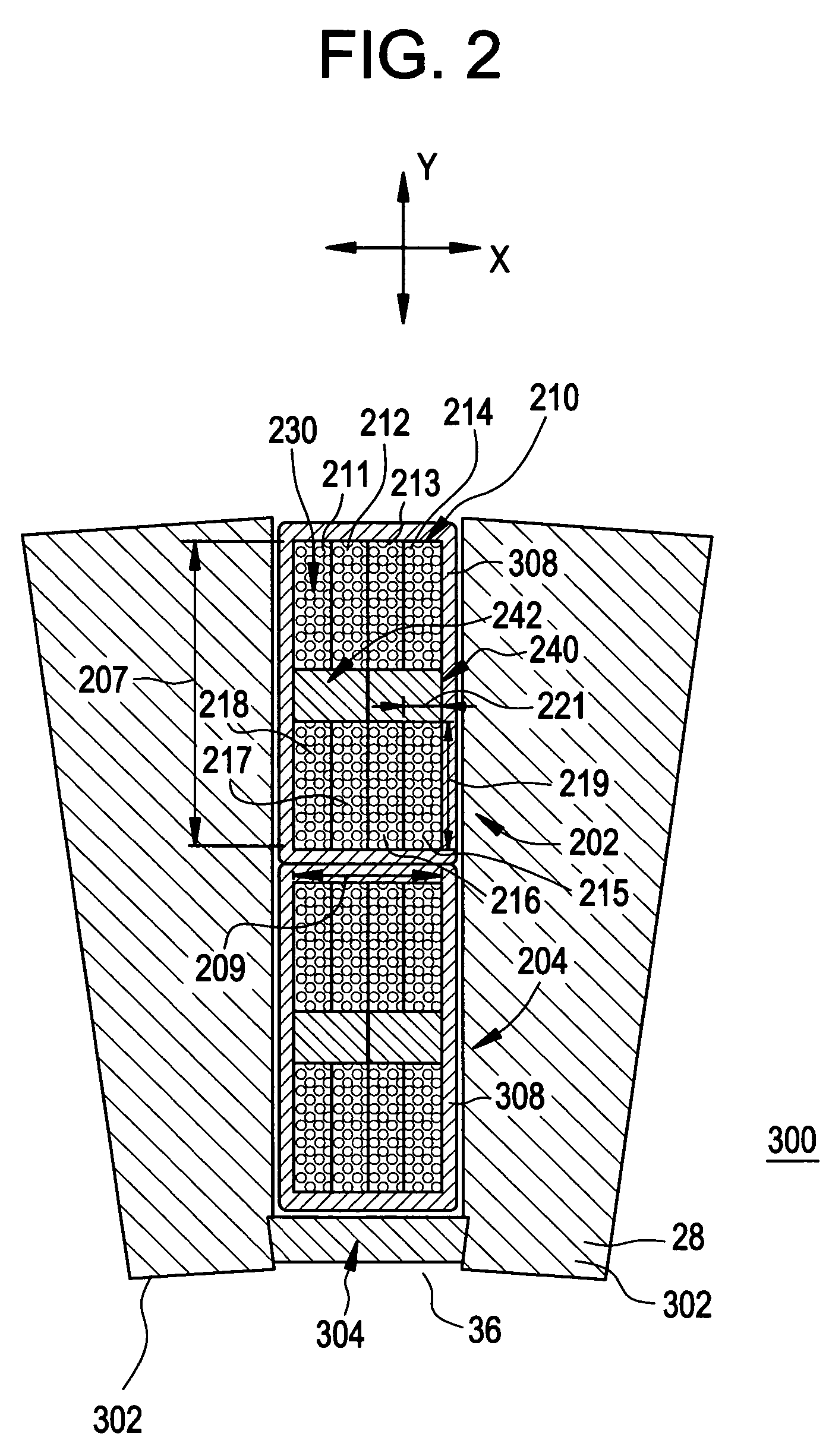
[0019]In high frequency electrical machines, a winding including at least one series of coils formed of multi-strand litz wire turns, and a cooling system for cooling the winding in which at least one cooling tube is provided for respective coils of the winding, with each turn of an individual coil transferring heat to the at least one cooling tube, where heat is transferred along respective individual strands of the multi-strand litz wire, and from the respective individual strands to the at least one cooling tube. The AC winding may be any winding of an electric machine through which power flows, for example, an armature winding or an AC fie...


PUM

PropertyMeasurementUnit
frequenciesaaaaaaaaaa
surface areaaaaaaaaaaa
heat transfer areaaaaaaaaaaa

Abstract

A winding of an electric machine is provided, where the winding includes at least one series of serially connected AC bars. Each AC bar includes a series of serially connected turns formed by litz wire having a plurality of strands, and at least one cooling tube. Individual strands of the plurality of strands are respectively positioned substantially adjacent to the at least one cooling tube at at least one transfer point for providing heat transfer from the respective individual strands to the at least one cooling tube.

Description

BACKGROUND OF THE INVENTION[0001]The present disclosure relates to AC windings of electric machines, and particularly, to cooling systems integrated with AC windings of high frequency electrical machines, and further, to a method of manufacture for making the AC windings.[0002]It is well known that the capacity and efficiency of electric machines, such as motors and generators, can be improved by providing appropriate cooling systems for dissipating heat generated during operation. A variety of cooling methods have evolved for minimizing the effects of generated heat.[0003]Known cooling methods include application of a cooling medium, such as air or a fluid to the exterior or a portion thereof of an armature winding, such as within a closed or open chamber housing the armature winding, or through conduits, such as pressurized or non-pressurized conduits contacting the exterior of the armature winding. Such approaches are illustrated, for example, in U.S. Pat. No. 3,609,420 issued Se...

Claims


Application Information

Patent Timeline
Patent Type & Authority Patents(United States)
IPC IPC(8): H02K1/32H01F27/28H02K3/04H02K3/14H02K3/24H02K3/34
CPCH02K3/24H02K3/14H01F27/2876
Inventor SIVASUBRAMANIAM, KIRUBALASKARIS, EVANGELOS TRIFONALEXANDER, JAMES PELLIGRINOSHAH, MANOJ RAMPRASAD
Owner GENERAL ELECTRIC CO
Learn More