Method for identifying measuring points in an optical measuring system

Inactive Publication Date: 2007-02-27
LEICA GEOSYSTEMS AG
View PDF20 Cites 15 Cited by
  • Summary
  • Abstract
  • Description
  • Claims
  • Application Information

AI Technical Summary

Benefits of technology

[0009]It is the object of the invention to provide a method for measuring point identification in an optical measurement system, wherein the method reduces the disadvantages described above for target associated identification using known patterns of code features. In particular, the inventive

Problems solved by technology

Such identification systems have some disadvantages.
Thus, large numbers of such features need a large amount of spa

Method used


Image

  • Method for identifying measuring points in an optical measuring system
  • Method for identifying measuring points in an optical measuring system
  • Method for identifying measuring points in an optical measuring system

Examples


Example

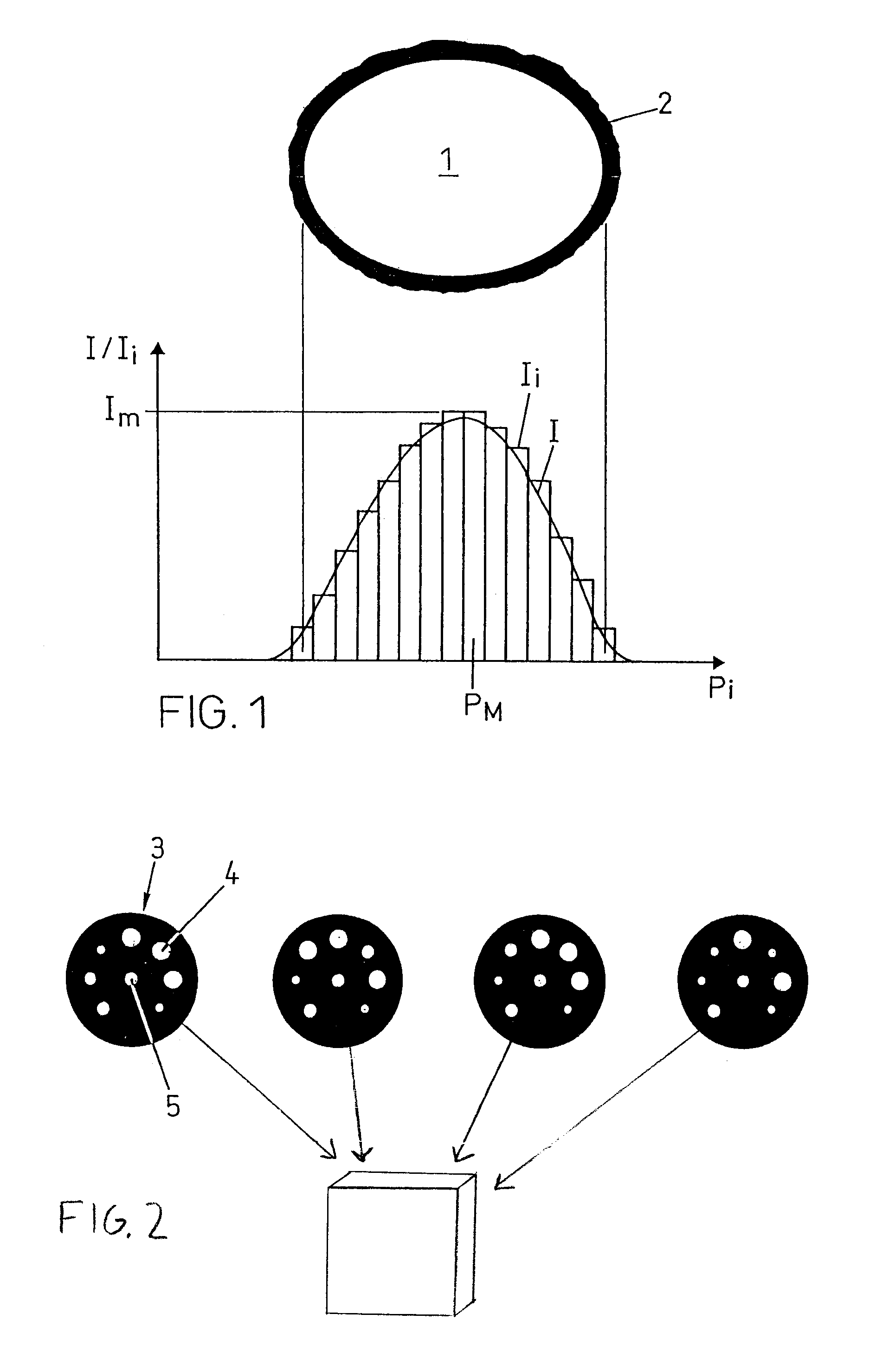
[0023]An upper portion of FIG. 1 shows a bright spot 1 on a darker background 2 which represents the image of a target with a specific intensity and size. A lower portion of FIG. 1 shows the intensity distribution I across the image of the target and the intensities Ii sensed by pixels Pi of a pixel detector in the area of the target image. As mentioned above, the intensity and / or size of the image may be determined by analysis of the intensities Ii of the pixels Pi comprised within the spot image. For determining only size, the number of the pixels Pi within the spot image can be determined. For only determining the intensity, it may be sufficient to register the maximum intensity IM sensed by pixel PM.

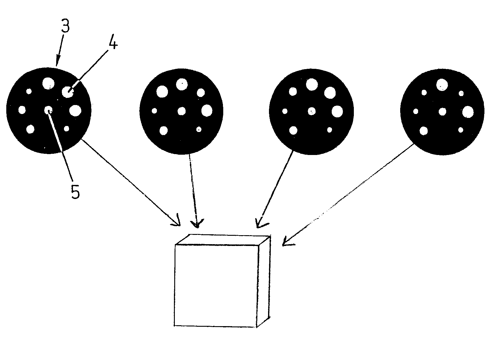
[0024]FIG. 2 shows four exemplified circular arrangements 3 of identification targets 4 disposed around a central target 5 marking a measuring point. The identification targets 4 have three different sizes, thereby allowing 37 permutations, i.e., 2187 permutations. Without complicati...


PUM


Abstract

In an optical measuring system for determining spatial position and orientation of objects, a plurality of measuring points on the object is registered by cameras, laser measuring devices or a combination thereof. For identifying the measuring points, one target of a specific intensity and/or size or a predetermined pattern (3) of a plurality of targets (4) having specific differing intensities and/or sizes is associated with each measuring point. The intensities and/or sizes of the targets are detected in a pixel image of the target (4) by summing up intensities sensed by pixels included in the image of the target. The targets are light emitting devices consuming differing amounts of energy, reflecting, black or white spots of differing diameter or spots of differing shades of gray or other suitable color.

Description

BACKGROUND OF THE INVENTION[0001]1. Field of the Invention[0002]The invention relates to the field of metrology and more particularly relates to a method for identifying measuring points in an optical measuring system in which a plurality of active or passive targets is used for marking measuring points.[0003]2. Description of Related Art[0004]Optical measuring systems are used for determining the position and orientation of objects in a three dimensional space, as well as for determining two dimensional deformation or three dimensional shape. For this purpose, optical measuring devices, such as cameras, laser measuring devices (e.g. laser trackers) or combinations thereof, are aimed towards the object to be measured and the spatial position of selected points (measuring points) on the object surface are registered. The data gained from such registration is then subjected to suitable computation from which data regarding the spatial position of the selected points is determined. The...

Claims


Application Information

Patent Timeline
IPC IPC(8): G01B11/14G01C15/06G01B11/00G01B11/03G01C11/00G01C15/02
CPCG01B11/00G01C15/02G01C11/00
Inventor CLARKE, TIMOTHY ALANWANG, XINCHI
Owner LEICA GEOSYSTEMS AG
Why Eureka
Try Eureka