Fiber optic drop cables suitable for outdoor fiber to the subscriber applications

a technology of fiber optic drop cables and outdoor fiber, applied in the direction of optics, fibre mechanical structures, instruments, etc., can solve the problems of limited bandwidth, copper cables have drawbacks, and transmit a relatively limited amount of data,

Active Publication Date: 2007-02-27
CORNING OPTICAL COMM LLC
View PDF29 Cites 81 Cited by
  • Summary
  • Abstract
  • Description
  • Claims
  • Application Information

AI Technical Summary

Problems solved by technology

However, copper cables have drawbacks because they are large, heavy, and can only transmit a relatively limited amount of data.
In other words, subscribers have a limited amount of available bandwidth due to the constraints of copper cables in the communication network.
But there are certain obstacles that make it challenging and / or expensive to route optical waveguides / optical cables deeper into the communication network, i.e., closer to the subscriber.
These designs worked well for the long-haul application but are not suitable for subscriber applications.
However, these rigid strength members make the fiber optic cable relatively stiff, thereby inhibiting characteristics such as slack storage and craft-friendliness.
Fiber optic cables also have used strength members such as conventional fiberglass yarns or aramid fibers, these strength members provide tensile strength and result in a flexible cable, but generally speaking do not provide anti-buckling strength for the cable.
Additionally, conventional fiberglass yarns or aramid fibers do not provide enough coupling to the cable for adequate clamping performance.
By way of example, aramid fiber strength members are able to migrate within the clamp relative to the jacket so that forces can be transferred to the optical fibers causing high levels of optical attenuation and in extreme cases can cause the optical fiber to be pulled-out from the optical connector.
Consequently, cable designs using conventional fiberglass yarns or strength members are not suitable for the rigors of outdoor drop cable applications since the temperature variations and / or clamping arrangements cause elevated levels of attenuation or cable failure, which are unacceptable.
Thus, the prior art cables do not meet all of the requirements for a drop cable that is suitable for routing optical waveguides to the subscriber.

Method used


Image

  • Fiber optic drop cables suitable for outdoor fiber to the subscriber applications
  • Fiber optic drop cables suitable for outdoor fiber to the subscriber applications
  • Fiber optic drop cables suitable for outdoor fiber to the subscriber applications

Examples


Embodiment Construction

[0021]The present invention will now be described more fully hereinafter with reference to the accompanying drawings showing preferred embodiments of the invention. The invention may, however, be embodied in many different forms and should not be construed as limited to the embodiments set forth herein; rather, these embodiments are provided so that the disclosure will fully convey the scope of the invention to those skilled in the art. The drawings are not necessarily drawn to scale but are configured to clearly illustrate the invention.

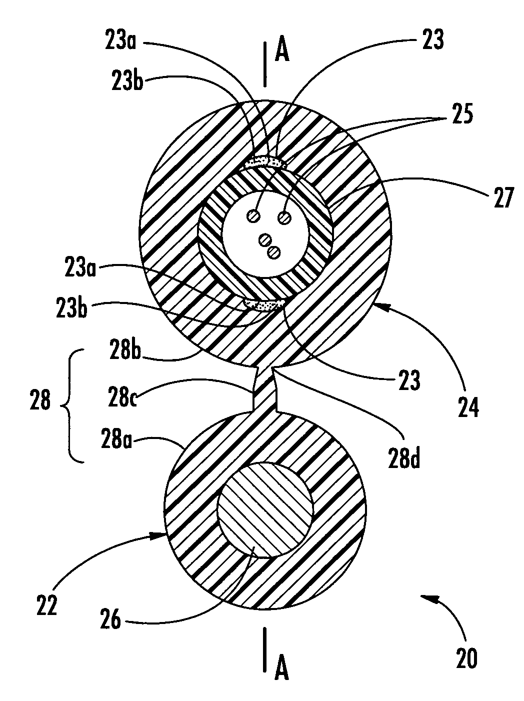
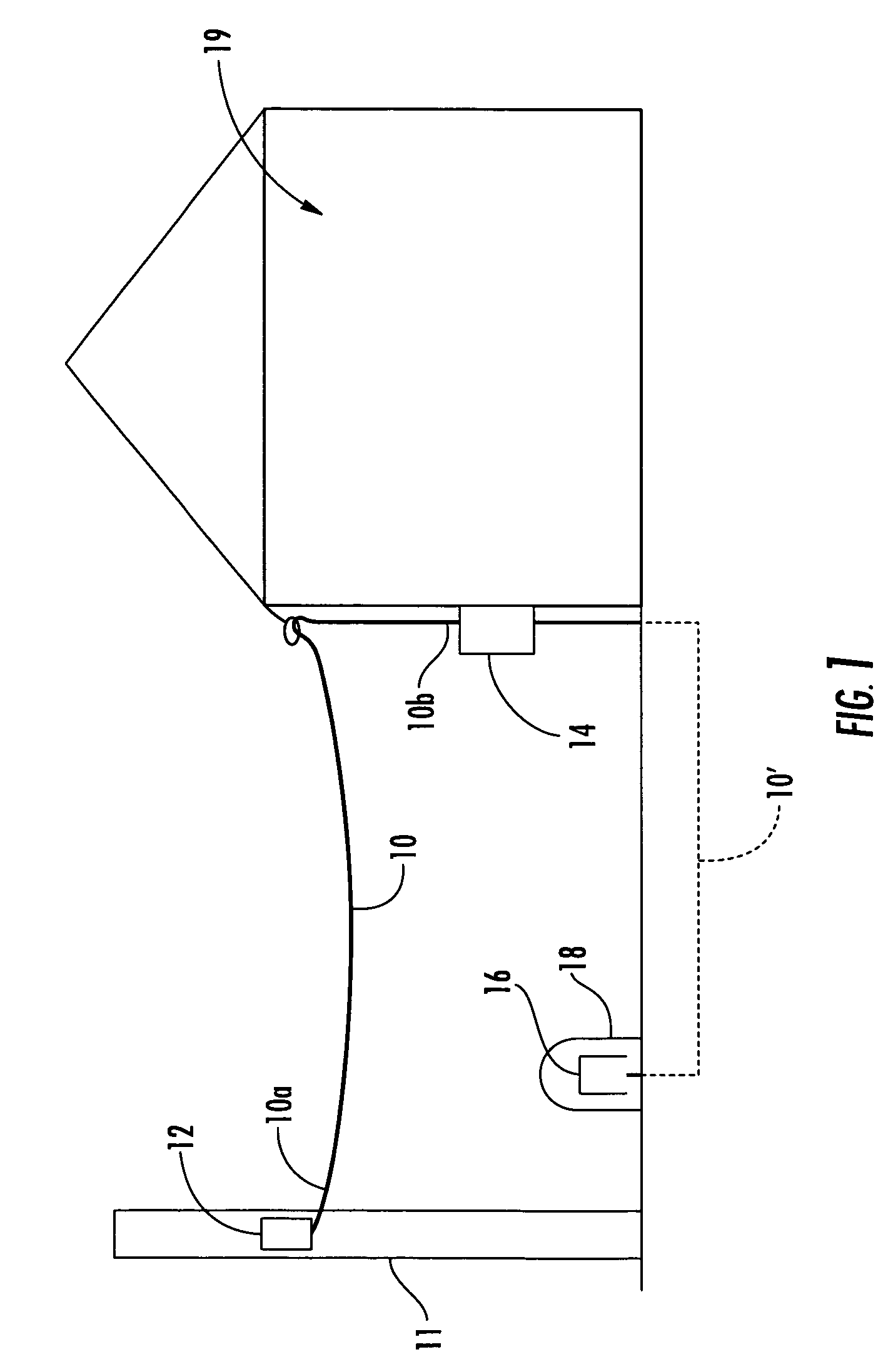
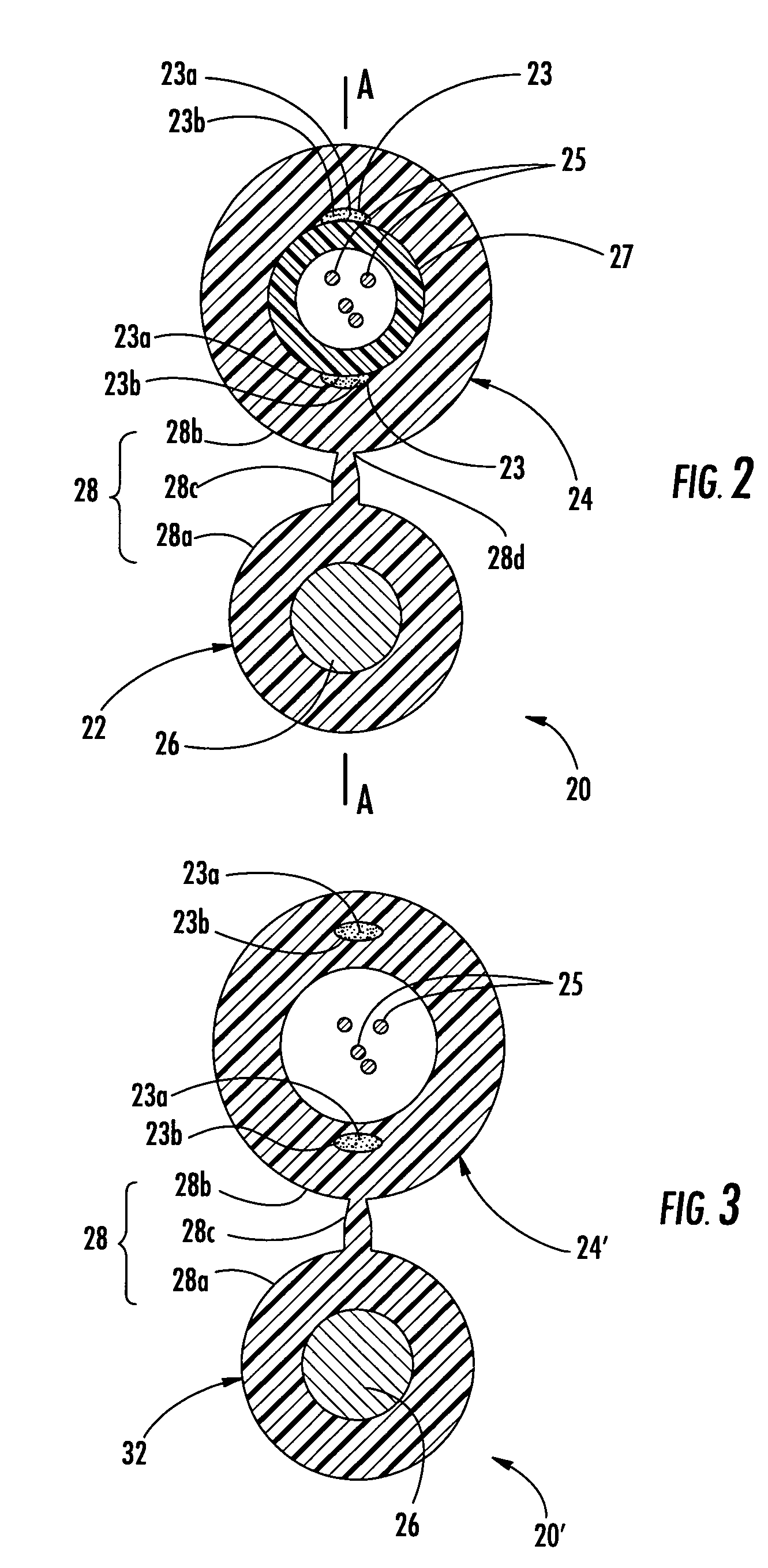
[0022]Illustrated in FIG. 2 is an exemplary fiber optic drop cable 20. (hereinafter cable 20) according to one embodiment of the present invention. Cable 20 is a figure-eight design that includes a messenger section 22 and a carrier section 24 having at least one roving 23 and at least one optical waveguide 25 such as an optical fiber therein. As depicted, optical waveguides 25 are loose, but they may have other configurations. Messenger section 22 ...


PUM


Abstract

A fiber optic drop cable including at least one optical waveguide, at least one roving, and a cable jacket. In one embodiment, the at least one roving includes a resin matrix having a water-based acrylic composition that includes an ethylene-acrylic acid and a water-swellable component. The resin matrix has a percent by weight of about 10 percent or less of the flexible roving so that the at least of one roving is at least partially bonded with the cable jacket, thereby inhibiting buckling of the cable jacket. In another embodiment, a plurality of rovings are arranged in clusters in the cable for influencing the bonding between the rovings and cable jacket. Also, disclosed is a protective casing for protecting and routing optical fibers along with preconnectorized cable assemblies.

Description

RELATED APPLICATIONS[0001]The present application is a Continuation-In-Part (CIP) of U.S. Ser. No. 10 / 809,619 filed on Mar. 25, 2004 now U.S. Pat. No. 7,035,513, the disclosure of which is incorporated herein by reference in its entirety. The present application is also related to U.S. patent application Ser. No. 11 / 099,864 respectively titled “Protective Casings for Optical Fibers” and filed on even date herewith.FIELD OF THE INVENTION[0002]The present invention relates generally to fiber optic drop cables. More specifically, the invention relates to low-cost fiber optic drop cables that are craft-friendly and preserve optical performance in outdoor applications such as fiber to the subscriber.BACKGROUND OF THE INVENTION[0003]Communication networks are used to transport a variety of signals such as voice, video, data transmission, and the like. Traditional communication networks use copper wires in cables for transporting information and data. However, copper cables have drawbacks ...

Claims


Application Information

Patent Timeline
Patent Type & Authority Patents(United States)
IPC IPC(8): G02B6/44G02B6/00
CPCG02B6/4433G02B6/3887G02B6/3849G02B6/3867G02B6/4494G02B6/3888G02B6/3889G02B6/38875G02B6/44384
Inventor HURLEY, WILLIAM C.SEDDON, DAVID A.MOHLER, JAMES D.
Owner CORNING OPTICAL COMM LLC
Why Eureka
Try Eureka