Telemetry system and method for acoustic arrays

a technology of acoustic arrays and telemetry, applied in the field of telemetry systems, can solve the problems of increasing outboard power dissipation, increasing the cost of hull penetration, and insufficient current conventional duplex fiber optic telemetry links for future large bandwidth acoustic arrays

Inactive Publication Date: 2007-02-27
LOCKHEED MARTIN CORP
View PDF21 Cites 22 Cited by
  • Summary
  • Abstract
  • Description
  • Claims
  • Application Information

AI Technical Summary

Problems solved by technology

Current conventional duplex fiber optic telemetry links are inadequate for future large bandwidth acoustic arrays.
Hull penetrations are expensive and generally undesirable.
In addition, having complete optical transmission and receiving capabilities in each OBE bottle increases outboard power dissipation.
Expanding existing telemetry systems, such as the system summarized above, results in additional problems.
Adding OBE bottles requires additional undesirable hull penetrations and results in even greater outboard power dissipation.
TAXI is an older protocol that does not work well for large sensor arrays.
It appears unlikely that vendors will continue to produce TAXI chipsets.

Method used


Image

  • Telemetry system and method for acoustic arrays
  • Telemetry system and method for acoustic arrays
  • Telemetry system and method for acoustic arrays

Examples


Embodiment Construction

[0019]In the following detailed description of the preferred embodiments, reference is made to the accompanying drawings, which form a part hereof, and in which is shown by way of illustration specific embodiments in which the invention may be practiced. It is to be understood that other embodiments may be utilized and structural or logical changes may be made without departing from the scope of the present invention. The following detailed description, therefore, is not to be taken in a limiting sense, and the scope of the present invention is defined by the appended claims.

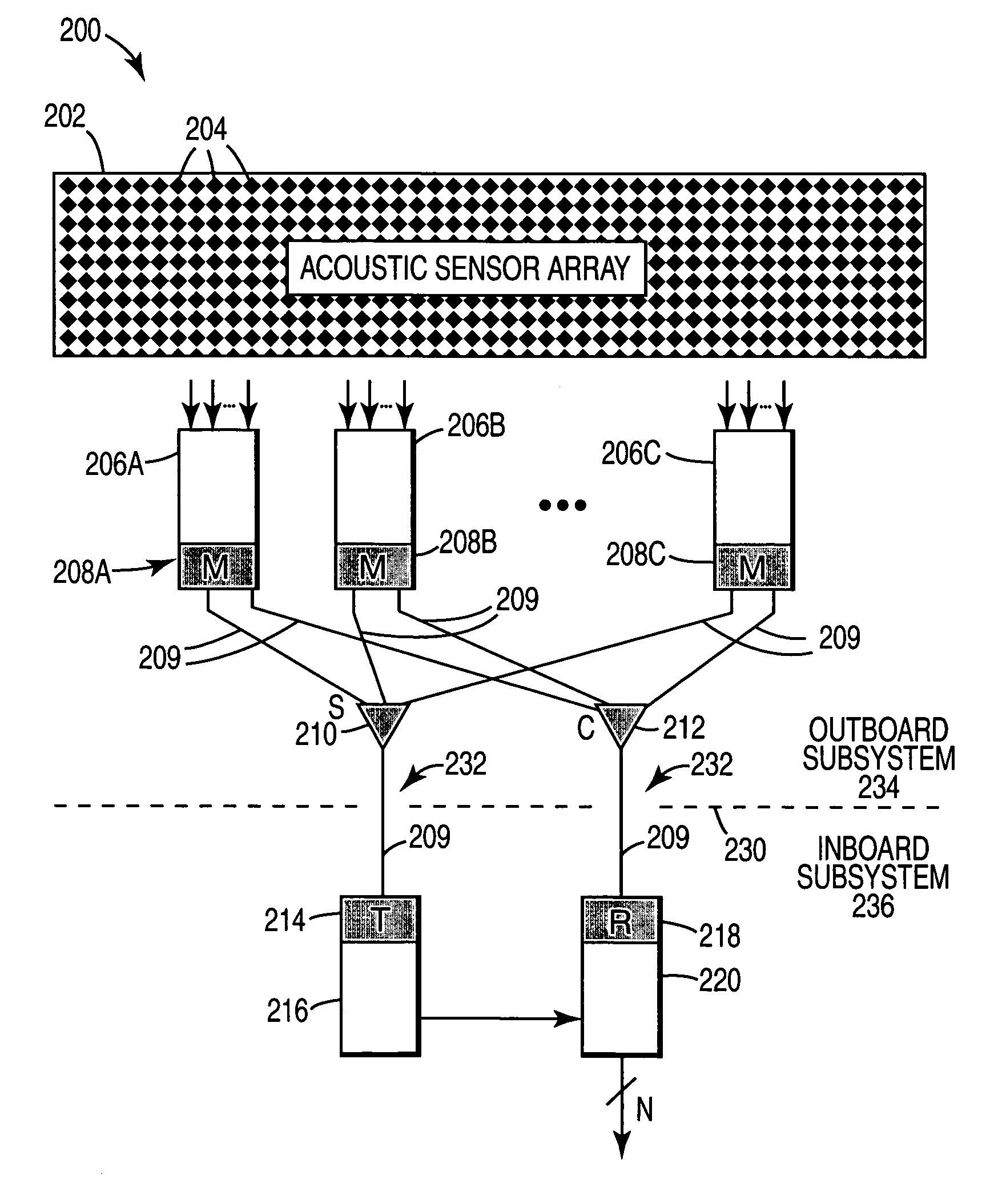
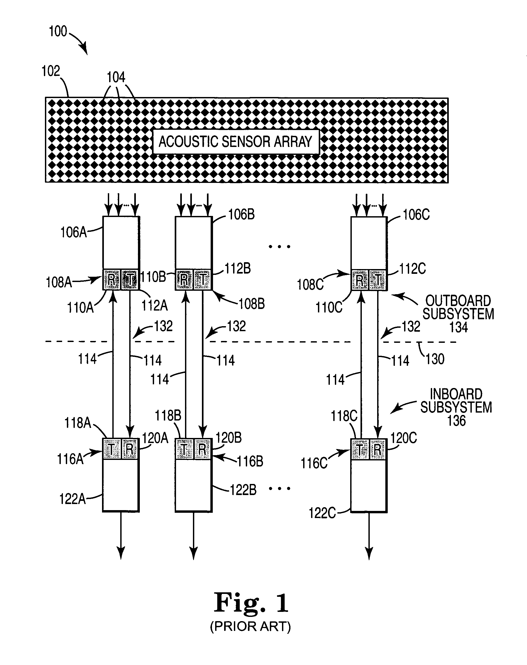
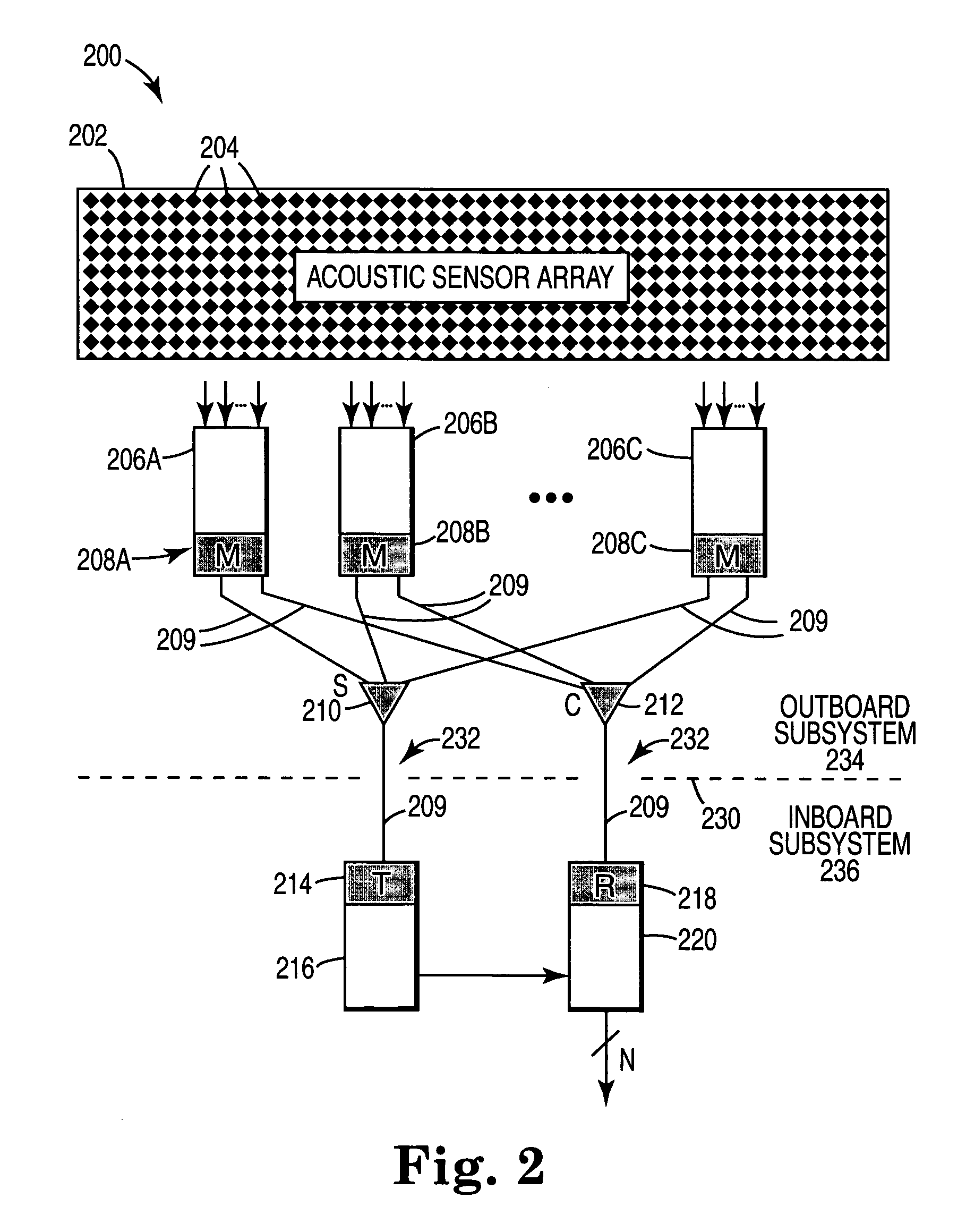
[0020]FIG. 1 is a block diagram illustrating major components of a prior art telemetry system. Telemetry system 100 is an underwater acoustic telemetry system that may be used in a submersible vehicle, such as a submarine, and which may be used to determine the position of a submersible vehicle relative to an acoustic network.

[0021]Telemetry system 100 includes acoustic sensor array 102, outboard electronic (OBE...


PUM


Abstract

A telemetry system includes a plurality of acoustic sensors for receiving acoustic information and generating analog signals based on the received acoustic information. A first plurality of subsystems is coupled to at least a subset of the plurality of acoustic sensors. The first plurality of subsystems is configured to receive the analog signals from the acoustic sensors and generate digital values based on the received analog signals. The system includes a first optical splitter. A first optical transmitter transmits a first set of optical pulses to the first optical splitter. The first optical splitter is configured to transmit the first set of optical pulses to each subsystem in the first plurality of subsystems. Each subsystem in the first plurality of subsystems is configured to modulate the first set of optical pulses based on the generated digital values and thereby generate a modulated optical pulse stream. A first optical combiner receives and combines the modulated optical pulse stream from each subsystem in the first plurality of subsystems, thereby generating a combined modulated optical pulse stream. A first optical receiver receives the combined modulated optical pulse stream from the first optical combiner. The first optical receiver is configured to generate electrical signals based on the received combined modulated optical pulse stream.

Description

CROSS REFERENCE TO RELATED APPLICATIONS[0001]This Non-Provisional Utility Patent Application claims the benefit of the filing date of U.S. Provisional Application Ser. No. 60 / 203,275, filed May 10, 2000, entitled “TELEMETRY FOR LARGE ACOUSTIC ARRAYS”.THE FIELD OF THE INVENTION[0002]This invention relates generally to telemetry systems. This invention relates more particularly to a telemetry system that uses time division multiplexing for large acoustic arrays.BACKGROUND OF THE INVENTION[0003]The word “telemetry” generally refers to communications systems that make measurements at remote or inaccessible points, and transmit these measurements to receiving equipment where they are monitored, recorded, and displayed. Telemetric systems typically include one or more measuring / transmitting instruments, a medium of transmission, a receiver, and recording and / or display equipment. The measuring / transmitting instrument is usually a transducer, which converts physical stimuli into electrical...

Claims


Application Information

Patent Timeline
Patent Type & Authority Patents(United States)
IPC IPC(8): H04B10/00H04J4/00G01V1/00G01V1/22G01V1/38
CPCG01V1/001G01V1/3817G01V1/22
Inventor TOWNSEND, VANWINKLE VAN T.
Owner LOCKHEED MARTIN CORP
Why Eureka
Try Eureka