Compressor, particularly in an exhaust gas turbocharger for an internal combustion engine

a technology of exhaust gas and turbocharger, which is applied in the field of compressors, can solve the problems of large adjustment movements that cannot be achieved, and the accuracy of guide vane position adjustment cannot be guaranteed, so as to achieve small and more accurately controllable adjustment forces, small number of building components, and simple design

Inactive Publication Date: 2007-03-06
DAIMLER AG
View PDF9 Cites 15 Cited by
  • Summary
  • Abstract
  • Description
  • Claims
  • Application Information

AI Technical Summary

Benefits of technology

[0008]In this way, the adjustment force for changing the pivot position of the guide vanes is not applied to the guide vane pivot shaft, but is directly transmitted to the guide vanes at a distance from the guide vane pivot shaft whereby smaller and more accurately controllable adjustment forces are required for the adjustment of the guide vanes. Expediently, the guide vanes which are annularly uniformly distributed around the compressor wheel are engaged by adjustment elements particularly at their radially outer ends which are disposed at a larger distance from the center of the diffuser geometry than the guide vane shafts. In this embodiment, the guide vanes are advantageously supported on a bearing ring, particularly they are engaged by the bearing ring only at one side thereof. With such an engagement of the guide vanes only at one side of the compressor diffuser in the compressor wheel discharge area, the possibility of jamming of the guide vanes is eliminated which, with a double-sided support on the opposite diffuser walls could possibly occur because of the substantial temperature differences between the diffuser walls.
[0009]Another advantage of the arrangement according to the invention resides in the simple design and in the small number of building components required, particularly the relatively small number of movable parts. As a result, undesired leakages, particularly in the area of the support shaft penetrations are reduced and the efficiency of the compressor is improved.
[0010]In accordance with a preferred embodiment of the invention, the guide vanes are fork-like shaped at their ends remote from the guide vane shafts so that they have two spaced tines between which the adjustment element of the adjustment ring extends. The adjustment element is preferably an adjustment pin which is firmly mounted to the adjustment ring and which, with a rotation of the adjustment ring, adjusts the pivot position of the guide vanes, all by the same angle as desired. This simple arrangement has been found to operate with high reliability.

Problems solved by technology

Large adjustment movements cannot be accomplished with this adjustment arrangement and an accurate adjustment of the guide vane positions cannot be ensured.

Method used


Image

  • Compressor, particularly in an exhaust gas turbocharger for an internal combustion engine
  • Compressor, particularly in an exhaust gas turbocharger for an internal combustion engine
  • Compressor, particularly in an exhaust gas turbocharger for an internal combustion engine

Examples


Embodiment Construction

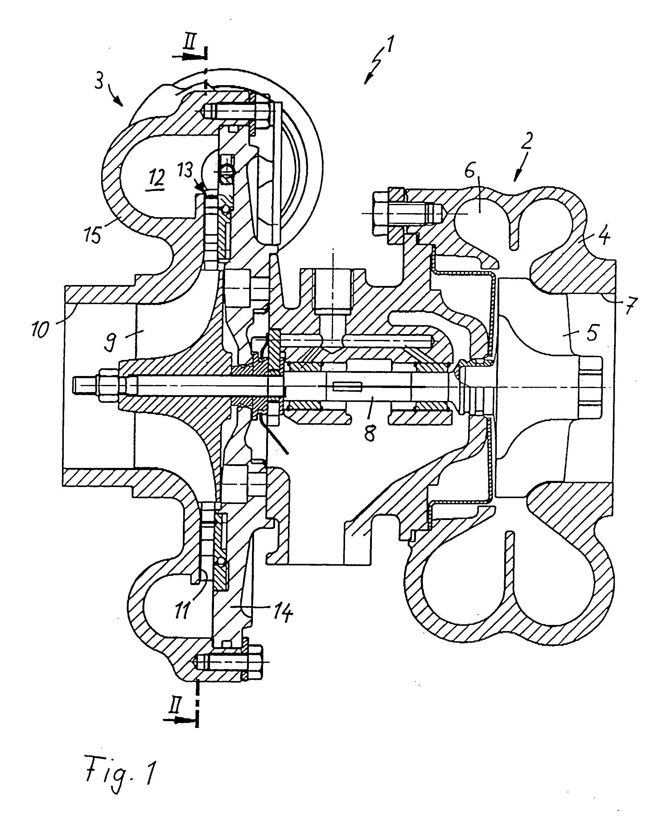
[0017]FIG. 1 shows an exhaust gas turbocharger 1 as it is expediently used in connection with internal combustion engines. It comprises an exhaust gas turbine 2, which is arranged in the exhaust duct of the internal combustion engine and a compressor 3, which is disposed in the intake duct of the internal combustion engine. The exhaust gas turbine 2 includes a turbine housing 4, and a turbine wheel 5, which is driven by the exhaust gases of the internal combustion engine and to which the exhaust gas discharged from the internal combustion engine under pressure is supplied via a spiral inlet passage 6. The exhaust gas is discharged from the exhaust gas turbine 2 axially via a discharge duct 7. The rotational movement of the turbine wheel is transmitted, via a shaft 8, to a compressor wheel 9 in the compressor housing 15. By the rotation of the compressor wheel 9 combustion air supplied by way of an inlet passage 10 is compressed to an increased charge pressure, at which pressure the ...


PUM


Abstract

In a compressor particularly of an exhaust gas turbocharger of an internal combustion engine having a compressor wheel rotatably supported in a compressor housing which includes a diffuser structure with an adjustable diffuser geometry comprising guide vanes pivotally supported, an adjustment ring is provided with engagement elements which engage forked end structures of the guide vanes at the outer ends of the guide vanes opposite the pivotal guide vane support so that the pivot position of the guide vanes can be adjusted by rotation of the adjustment ring.

Description

[0001]This is a Continuation-In-Part Application of International Application PCT / EP03 / 08741 filed Aug. 7, 2003 and claiming the priority of German application 102 38 658.7 filed Aug. 23, 2002.BACKGROUND OF THE INVENTION[0002]The invention relates to a compressor, particularly in an exhaust gas turbocharger, for an internal combustion engine with a compressor wheel rotatably supported in a compressor housing and a diffuser which is arranged in the compressor housing upstream of the compressor wheel and has a variable diffuser geometry formed by adjustable guide vanes.[0003]In such a compressor as described for example in U.S. Pat. No. 5,207,559, fresh air is supplied to the compressor by way of a compressor supply channel and is compressed by a compressor wheel in the compressor housing and is then conducted downstream of the compressor wheel through a diffuser. The compressor wheel is driven via a shaft by a turbine with a turbine wheel to which gas under pressure is supplied.[0004...

Claims


Application Information

Patent Timeline
Patent Type & Authority Patents(United States)
IPC IPC(8): F01D17/16F03B1/04F04D27/02F04D29/46
CPCF01D17/165F04D29/462F04D27/0246F05D2220/40F05D2250/52
Inventor DAUDEL, HELMUTLOFFLER, PAULSCHENKEL, STEPHANSPURK, JOSEPH
Owner DAIMLER AG
Why Eureka
Try Eureka