Eureka AIR delivers breakthrough ideas for toughest innovation challenges, trusted by R&D personnel around the world.

Torque vectoring gear drive apparatus

a gear drive and torque vectoring technology, applied in the direction of gears, control devices, driver input parameters, etc., can solve the problems of reducing engine power and/or selectively, reducing engine power and/or engine power, and reducing engine power in the vehicle stability system to correct the problem, so as to reduce the understeer and avoid collision

Active Publication Date: 2007-03-06
DANA AUTOMOTIVE SYST GRP LLC
View PDF8 Cites 74 Cited by
  • Summary
  • Abstract
  • Description
  • Claims
  • Application Information

AI Technical Summary

Benefits of technology

[0011]Therefore, the selectively operable speed gear assembly for the AWD motor vehicles in accordance with the present invention represents a novel arrangement of the AWD torque transfer provided with the speed gear assembly allowing torque vectoring so as to speed up first output shaft while slow down the second output shaft, or, alternatively, slow down the first output shaft while speed up the second output shaft. Such an arrangement of the speed gear assembly helps correct vehicle understeer and / or oversteer to help keep the vehicle on course and avoid a collision.

Problems solved by technology

Known prior AWD systems have generally required complex electronic sensors or other complex systems to monitor the slip or differentiation between the front output shaft and the rear output shaft or the front wheels and the rear wheels of a motor vehicle.
Typically, the known vehicle stability systems monitor the vehicle behavior based on a number of electronic sensors, and decrease engine power and / or selectively apply brakes to the appropriate wheels as needed for stabilizing the vehicle trajectory.
More specifically, if road conditions cause your vehicle to understeer, the vehicle stability system decreases engine power to correct the problem.
Moreover, while known transfer cases, including but not limited to those discussed above, have proven to be acceptable for various vehicular driveline applications, such devices are nevertheless susceptible to improvements that may enhance their performance and cost.

Method used


Image

  • Torque vectoring gear drive apparatus
  • Torque vectoring gear drive apparatus
  • Torque vectoring gear drive apparatus

Examples


Embodiment Construction

[0016]The preferred embodiment of the present invention will now be described with the reference to accompanying drawings.

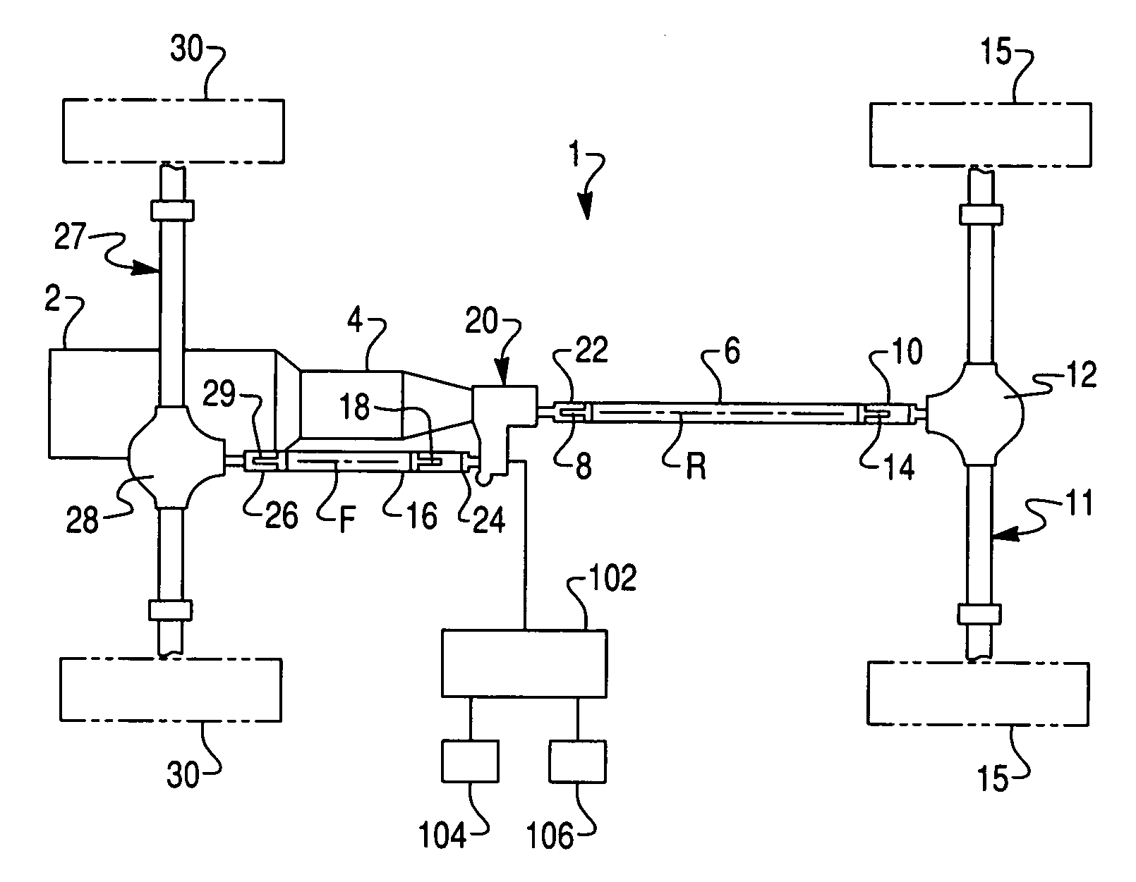
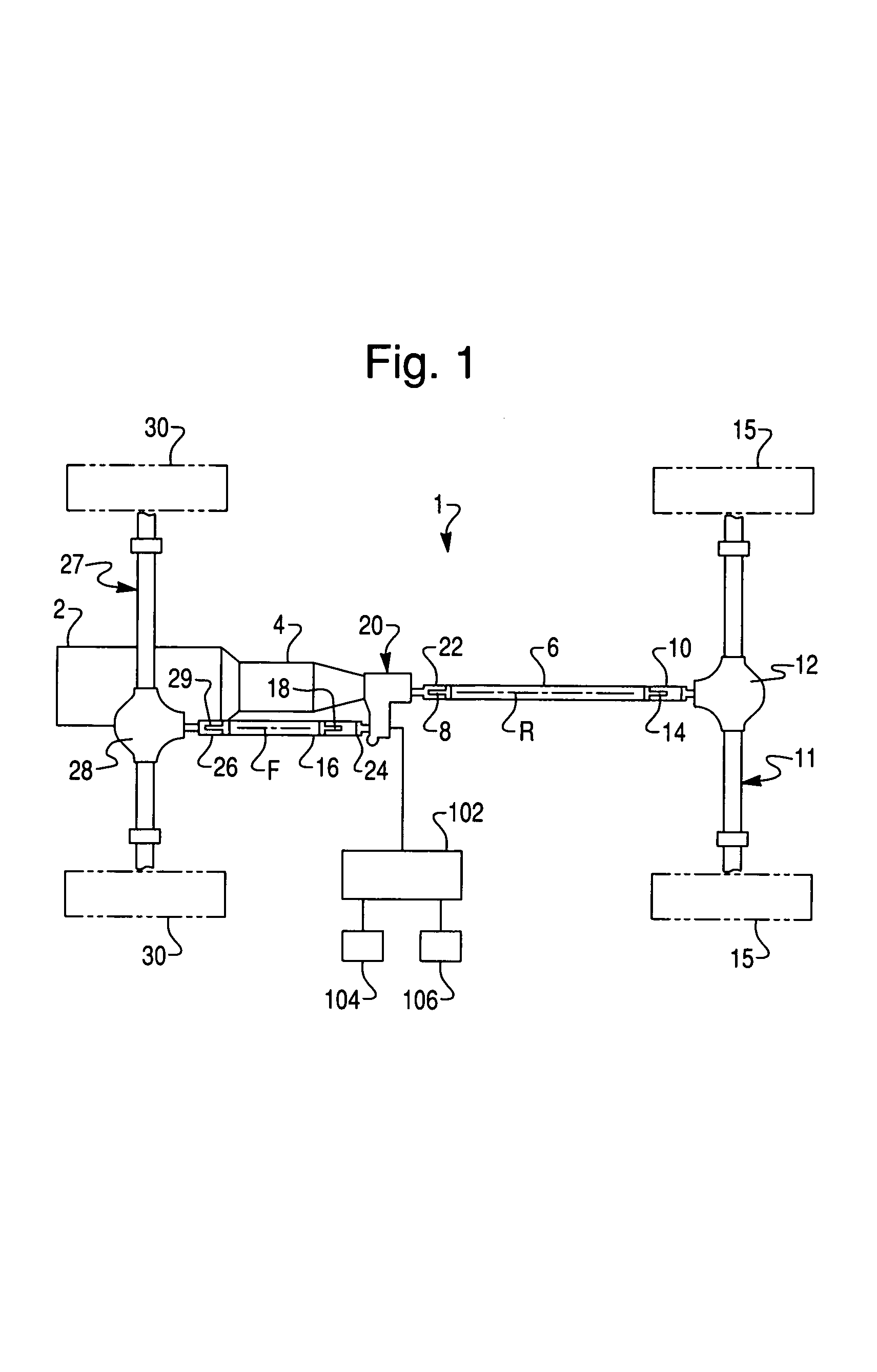
[0017]FIG. 1 schematically depicts a drivetrain 1 of an all-wheel drive (AWD) or four-wheel drive (4WD) motor vehicle in accordance with the present invention. The AWD drivetrain 1 comprises an internal combustion engine 2 (shown in phantom line) mounted to a front end of the motor vehicle and coupled to a transmission unit 4 (also shown in phantom line).

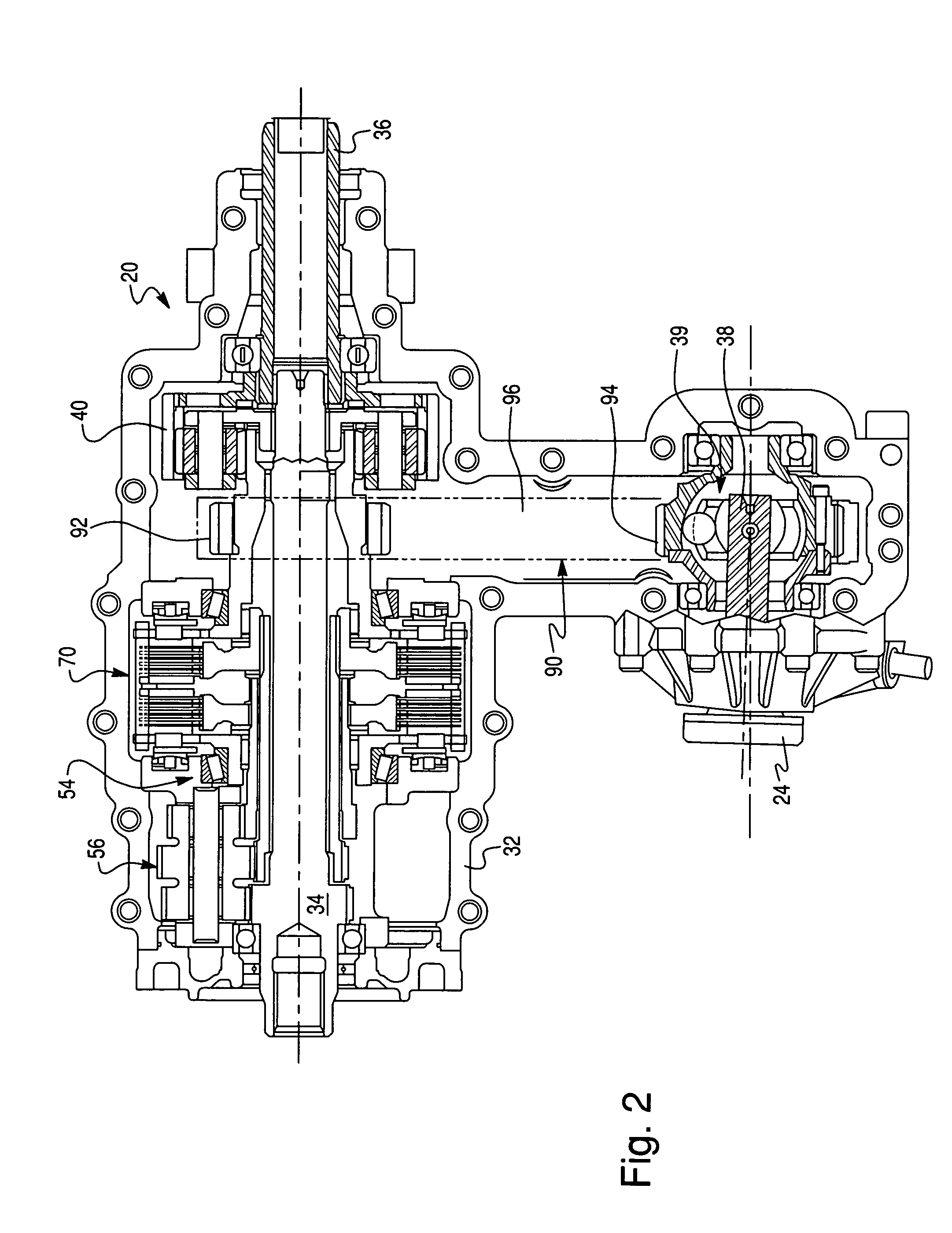
[0018]According to the preferred embodiment of the present invention, a torque transfer gear drive apparatus 20, commonly known in the art as or a transfer case, is secured to the rear of the transmission unit 4. The transmission unit 4 is provided with an output shaft that is coupled to an input shaft (referred to below in FIG. 2 as 34) of the transfer case 20. The transfer case 20 includes a rear coupling flange (or yoke) 22 that is coupled to a rear output shaft (referred to below in FIG. 2 as 36) of the trans...


PUM


Abstract

A torque vectoring gear drive apparatus for controlling drive torque distribution. The gear drive apparatus comprises an input shaft, first and second output shafts, a planetary interaxle differential unit for transmitting torque from the input shaft to the first and second output shafts, and a speed gear assembly provided for overriding said planetary interaxle differential unit. The planetary differential unit includes a planet carrier drivingly coupled to the input shaft and rotatably supporting at least one planet gear, a sun gear drivingly coupled to the at least one planet gear and a ring gear drivingly coupled the first output shaft, the sun gear drivingly coupled to the second output shaft. The speed gear assembly selectively couples the input shaft to the sun gear to define a first drive mode in which the sun gear is driven at a first speed.

Description

BACKGROUND OF THE INVENTION[0001]1. Field of the Invention[0002]The present invention relates to power transfer systems for controlling drive torque distribution, and more particularly to a torque vectoring gear drive apparatus including a planetary differential unit and a speed gear assembly for selectively varying a gear transmission ratio between an input shaft and output shafts.[0003]2. Description of the Prior Art[0004]Four-wheel drive (4WD) motor vehicles are becoming increasingly popular, especially “full-time” four-wheel drive systems called in the art as all-wheel drive (AWD) systems. In such AWD systems, torque transfer cases are typically provided with an inter-axle differential for dividing torque between front wheels and rear wheels of the motor vehicle. The inter-axle differential enables the front wheels and the rear wheels to rotate at different speeds, which occurs during normal turning of the motor vehicle or in the event that the front wheels and the rear wheels h...

Claims


Application Information

Patent Timeline
Patent Type & Authority Patents(United States)
IPC IPC(8): F16H37/08
CPCB60K17/3462B60K23/0808B60W2520/14B60W2540/18
Inventor BAXTER, JR., RALPH WOODWARD
Owner DANA AUTOMOTIVE SYST GRP LLC
Why Eureka
Eureka Blog
Learn More