Rear Suspension of Hydraulic Interconnected Torsion Elimination Suspension

A hydraulic and torsion suspension technology, applied in the suspension, interconnection system, transportation and packaging, etc., can solve the problems of severe torsional load, poor oil coupling and high cost of the car body, and achieve the elimination of torsional load of the car body and enhanced acceleration performance, the effect of improving grounding performance

Inactive Publication Date: 2016-08-31
JIANGSU UNIV
View PDF7 Cites 0 Cited by
  • Summary
  • Abstract
  • Description
  • Claims
  • Application Information

AI Technical Summary

Problems solved by technology

[0002] Four-wheel vehicles have redundant constraints. When the road surface undulation is close to or greater than the static deflection, the disadvantages of redundant constraints will become more prominent. For example, when the vehicle is driving on an uneven road, there may be two The wheel load tends to zero, while the two wheels on the other diagonal double the load and subject the body to severe torsional loads
However, the structure of the oil-gas spring is more complicated and the cost is higher. Since the working medium is high-pressure gas and oil, higher requirements are put forward for the surface roughness, assembly accuracy, wear resistance, and design of the sealing link of the relative moving parts, and special equipment is required. Inflatable equipment and operating procedures Inflate the air chamber in time to ensure airtightness During use, the gas is easy to leak slowly and maintenance is troublesome
However, the air spring coupling will not be able to instantly balance the internal pressure and eliminate excess load because the speed of gas transmission pressure is slower than that of oil. The effect of coupling is worse than that of oil coupling.

Method used


Image

  • Rear Suspension of Hydraulic Interconnected Torsion Elimination Suspension

Examples


Embodiment Construction

[0010] The present invention will be further described below in conjunction with accompanying drawing and embodiment.

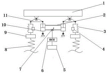
[0011] Such as figure 1 As shown, the rear suspension of the present invention includes a sprung mass 1 and a group of hydraulically interconnected torsion-removing components, which are respectively located at the bottom ends of both sides of the sprung mass 1. Spring 3, shock absorber 4, double-acting hydraulic cylinder 10, unobstructed pipeline 2, electronic control unit 6 and display screen 5; wherein, isosceles triangle with vertex angle greater than 120° for isosceles lever 11, unobstructed pipeline 2 is High-pressure pipeline.

[0012] The apex of the upper end of the equal arm lever 11 is hinged with the bottom ends on both sides of the sprung mass 1, and the upper end of the parallel body of the spring 3 and the shock absorber 4 and the upper end of the double-acting hydraulic cylinder 10 are respectively connected to the upper end of the equal arm ...


PUM


Abstract

The invention discloses a rear suspension of a hydraulic interconnected torsion eliminating suspension. The rear suspension comprises equal armed levers, springs, vibration absorbers, a double acting hydraulic cylinder, a smooth pipeline, an electric control unit and a display. The left and right cylinders experience equal force since the vertical force of the suspension on one side consistently penetrates the interconnection of the left and right cylinders through the serial connection of a rear-suspended hydraulic cylinder and a traditional suspension structure (interconnecting members of springs and absorbers), and accordingly the left and right parts of the rear suspension experience equal force. The direction of the force of the suspension is changed through the equal armed levers, so that the purpose of reducing the height of the rear suspension to be the same of the front traditional suspension can be achieved. The rear suspension has the advantages that grounding performances of tires are improved greatly, part of vehicle torsion load is eliminated effectively, and smoothness of driving and passing performances on rough roads are improved.

Description

technical field [0001] The invention relates to a vehicle suspension, in particular to a vehicle suspension that adopts hydraulic interconnection and minimizes suspension constraints. Background technique [0002] Four-wheel vehicles have redundant constraints. When the road surface undulation is close to or greater than the static deflection, the disadvantages of redundant constraints will become more prominent. For example, when the vehicle is driving on an uneven road, there may be two The wheel load tends to zero, while the two wheels on the other diagonal double the load and subject the body to severe torsional loads. Usually, this shortcoming is solved by reducing the stiffness of the suspension and increasing the dynamic stroke of the suspension, but these methods will bring about a reduction in the lateral angular stiffness and longitudinal angular stiffness, which greatly reduces the handling stability of the vehicle. The four-wheeled vehicle produces four vertical...

Claims


Application Information

Patent Timeline
Patent Type & Authority Patents(China)
IPC IPC(8): B60G21/073
CPCB60G21/06
Inventor 汪若尘吴涛孙泽宇孟祥鹏黄欢
Owner JIANGSU UNIV
Why Eureka
Try Eureka