Eureka AIR delivers breakthrough ideas for toughest innovation challenges, trusted by R&D personnel around the world.

Vacuum cleaner

Active Publication Date: 2007-03-06
DYSON TECH LTD
View PDF10 Cites 21 Cited by
  • Summary
  • Abstract
  • Description
  • Claims
  • Application Information

AI Technical Summary

Benefits of technology

[0009]By inhibiting operation of the releasing means when the collecting chamber is stowed on the chassis of the cleaner, it is not possible for a user to accidentally release the closure member. This avoids the mess which would result if the cleaner were operated with the closure member partially open or if the collecting chamber were removed from the chassis with the closure member partially open. Indeed, the manner in which the collecting chamber is supported on the chassis is such that a user may not be aware that they had inadvertently released the closure member until they removed the collecting chamber from the chassis.
[0011]Preferably the closure member remains coupled to the collecting chamber, such as by a pivotal coupling. Thus, a user does not need to struggle with refitting the closure member and there is no risk of the closure member falling into a dust bin or refuse sack along with the dirt and dust which is released from the collecting chamber.
[0012]It is convenient for the actuating member to be located adjacent a handle for carrying the collecting chamber. This allows a user to carry and empty the collecting chamber with one hand.
[0013]Preferably agitating means are provided for agitating dirt held within the collection area, the agitating means being operable by the releasing means. This helps to dislodge any dirt that may have become ‘stuck’ in the collection area. Also, a user does not need to separately operate the release and the agitating means.

Problems solved by technology

By inhibiting operation of the releasing means when the collecting chamber is stowed on the chassis of the cleaner, it is not possible for a user to accidentally release the closure member.
Indeed, the manner in which the collecting chamber is supported on the chassis is such that a user may not be aware that they had inadvertently released the closure member until they removed the collecting chamber from the chassis.

Method used


Image

  • Vacuum cleaner
  • Vacuum cleaner
  • Vacuum cleaner

Examples


Embodiment Construction

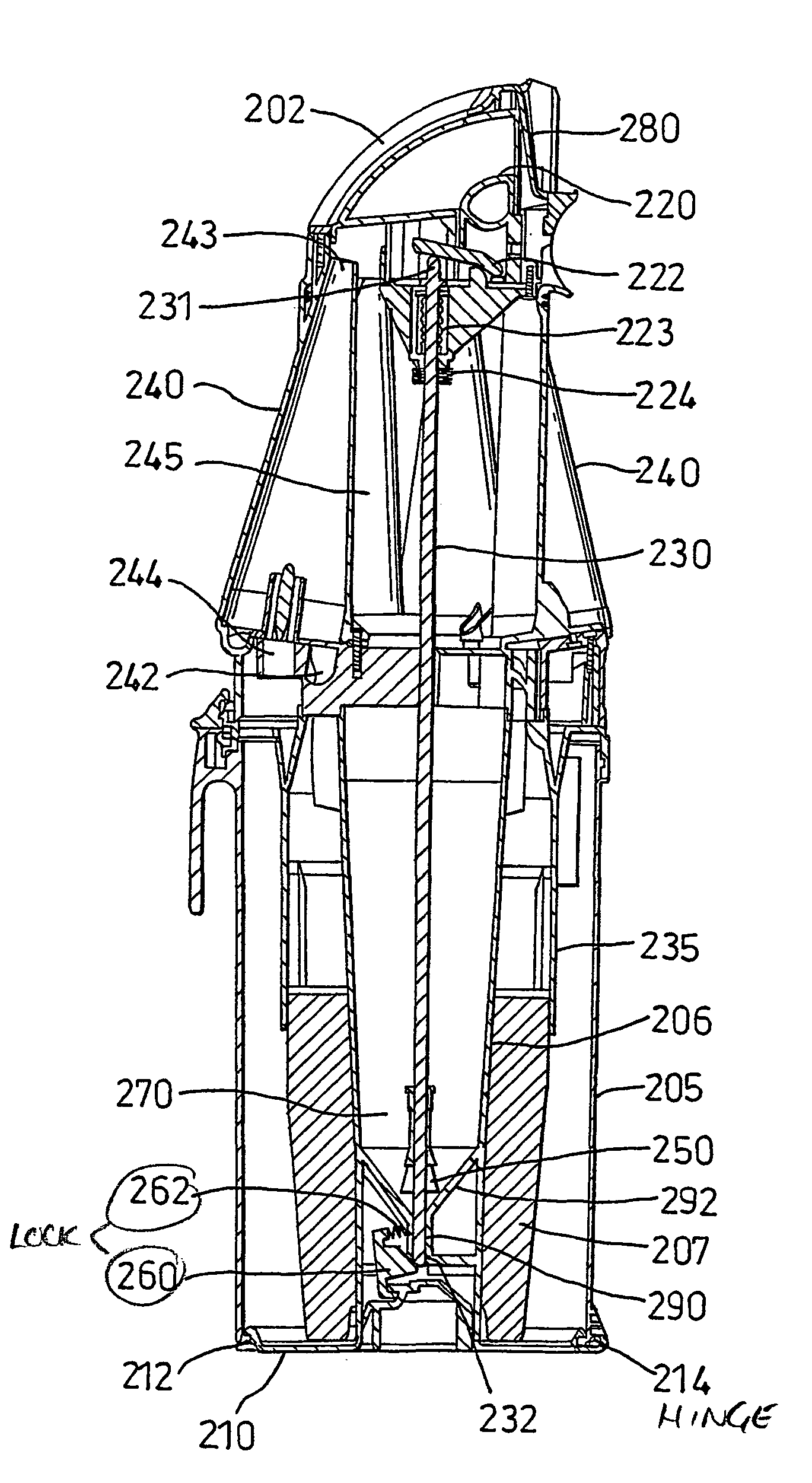
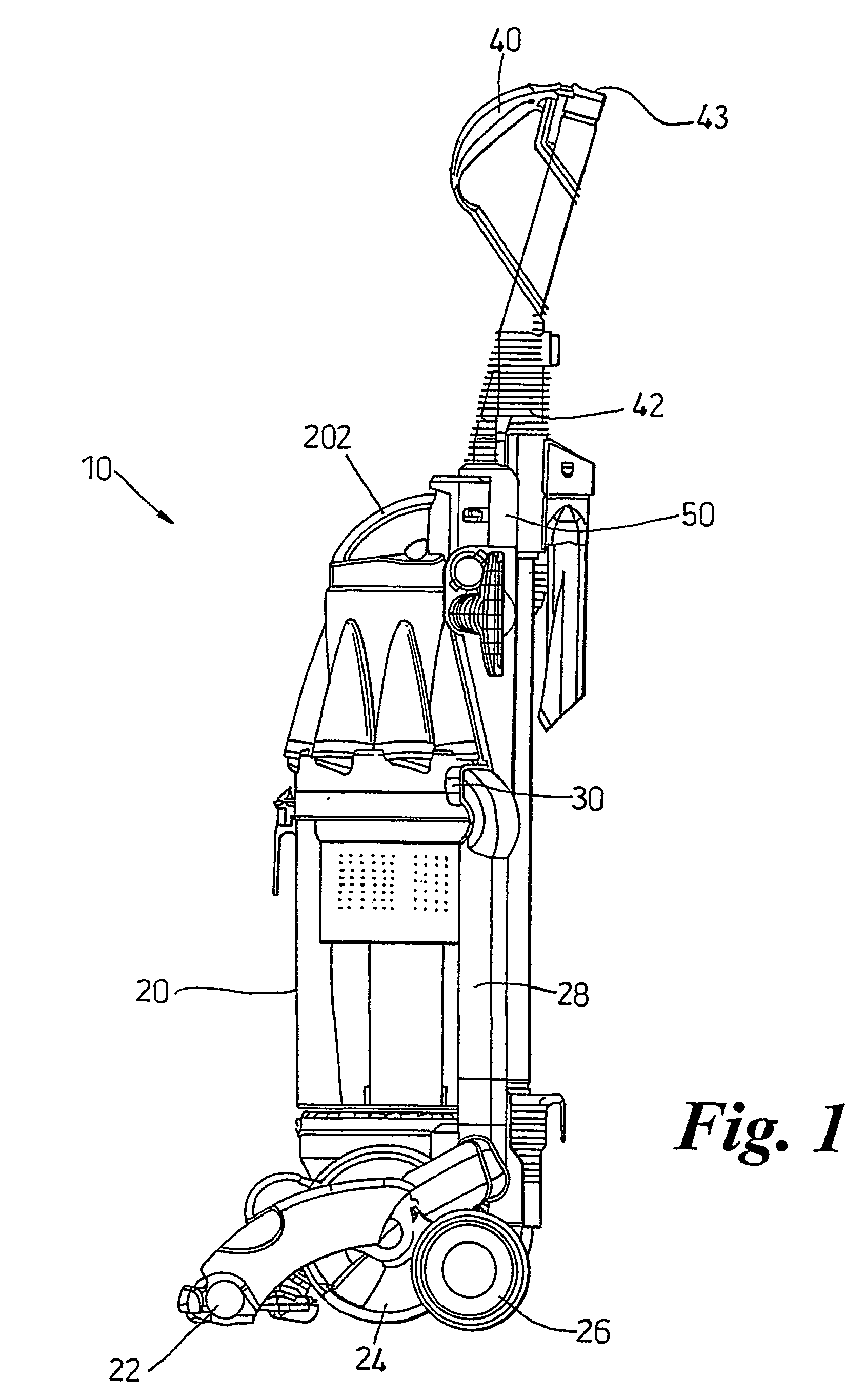
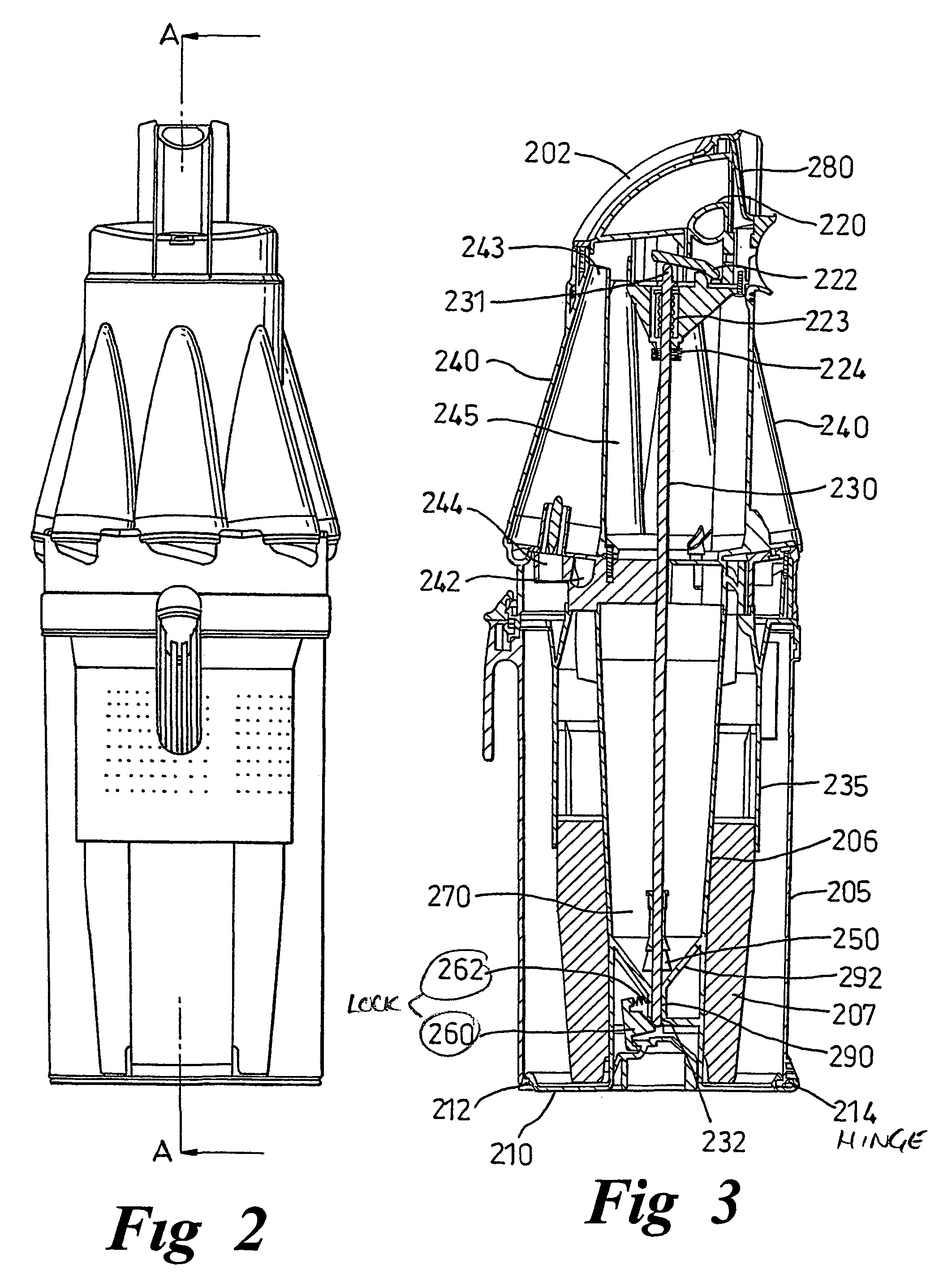
[0027]Referring to FIGS. 1 to 3, a vacuum cleaner 10 has a main chassis 50 which supports dirt and dust separation apparatus 20. The lower part of the cleaner 10 comprises a cleaner head 22 for engaging with the floor surface. The cleaner head has a downwardly facing suction inlet and a brush bar is mounted in the mouth of the inlet for agitating the floor surface. The cleaner head is pivotably mounted to a motor housing 24 which houses the motor and fan of the cleaner. Support wheels 26 are mounted to the motor housing for supporting the cleaner and allowing movement across a floor surface. A spine of the chassis 50 extends upwardly from the motor housing 24 to provide support for the components of the cleaner. A cleaning wand 42 having a second dirty air inlet 43 is connected by way of a hose (not shown) to the chassis at the base of the spine 50. The wand 42 is releasable from the spine 50 so as to allow a user to carry out above-the-floor cleaning and cleaning in places which ar...


PUM

PropertyMeasurementUnit
Forceaaaaaaaaaa
Areaaaaaaaaaaa

Abstract

A cyclonic vacuum cleaner includes a separating unit for separating dirt and dust from a dirt-laden airflow which is drawn in by the cleaner. The separating unit has a chamber with a collection area for collecting dirt and dust which is separated from the airflow. A base of the separating unit is movable between a closed position in which the closure member seals the chamber and an open position by operation of a releasing means. The releasing means is inhibited from releasing the base when the unit is stowed on the chassis of the cleaner.

Description

FIELD OF THE INVENTION[0001]This invention relates to a vacuum cleaner which incorporates a collecting chamber.BACKGROUND OF THE INVENTION[0002]Vacuum cleaners which separate dirt and dust from an airflow without the use of a filter bag, so-called bagless vacuum cleaners, are becoming increasingly popular. Most bagless cleaners use cyclonic or centrifugal separation to spin dirt and dust from the airflow. By avoiding the use of a filter bag as the primary form of separation, it has been found possible to maintain a consistently high level of suction, even as the collecting chamber fills with dirt.[0003]The principle of cyclonic separation in domestic vacuum cleaners is described in a number of publications including EP 0 042 723. In general, an airflow in which dirt and dust is entrained enters a first cyclonic separator via a tangential inlet which causes the airflow to follow a spiral or helical path within a collection chamber so that the dirt and dust is separated from the airfl...

Claims


Application Information

Patent Timeline
IPC IPC(8): B01D35/30A47L5/28A47L9/10A47L9/16
CPCA47L9/1625A47L9/1683A47L9/1641Y10S55/03
Inventor VUIJK, REMCO DOUWINUS
Owner DYSON TECH LTD
Why Eureka
Eureka Blog
Learn More