

Fuel tank venting system and an additional filter element therefor
a filter element and fuel tank technology, applied in the field of additional filter elements, can solve the problems of limited adsorption capacity, high production cost, and marked delay in the escape of gasoline vapor from the tank to the ambient atmosphere, and achieve enhanced reduction efficiency and reduced levels of hydrocarbon emissions.
- Summary
- Abstract
- Description
- Claims
- Application Information
AI Technical Summary
Benefits of technology
Problems solved by technology
Method used
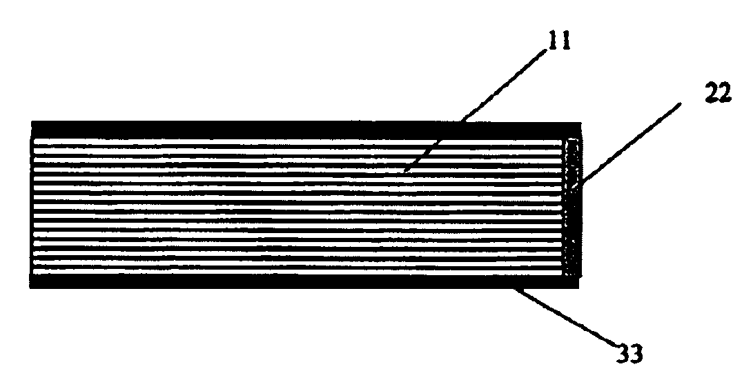
Image

Examples
Embodiment Construction
[0042]It will be noted at this point that the following aspects are generally crucial in terms of a functional tank venting system:
[0043]1. the emission from the main activated carbon filter is not to exceed a predetermined maximum value;
[0044]2. the additional filter element, in the event of a temperature increase from 20° C. to 42° C., must still have a sufficiently high residual capacity to receive the emissions from the main activated carbon filter; and
[0045]3. in a situation involving a very low level of loading from the main activated carbon filter it is the own emissions from the additional filter element that dominate. Those emissions from the additional filter element itself are not to exceed a maximum value in a heating cycle in the event of a temperature increase from 20° C. to 42° C.
[0046]As indicated hereinbefore, attainment of the first aspect listed above has already been implemented by the development of optimised activated carbon filters in the form of multi-chamber...
PUM
| Property | Measurement | Unit |
|---|---|---|
| temperature | aaaaa | aaaaa |
| temperature | aaaaa | aaaaa |
| temperature | aaaaa | aaaaa |
Abstract
Description
Claims
Application Information