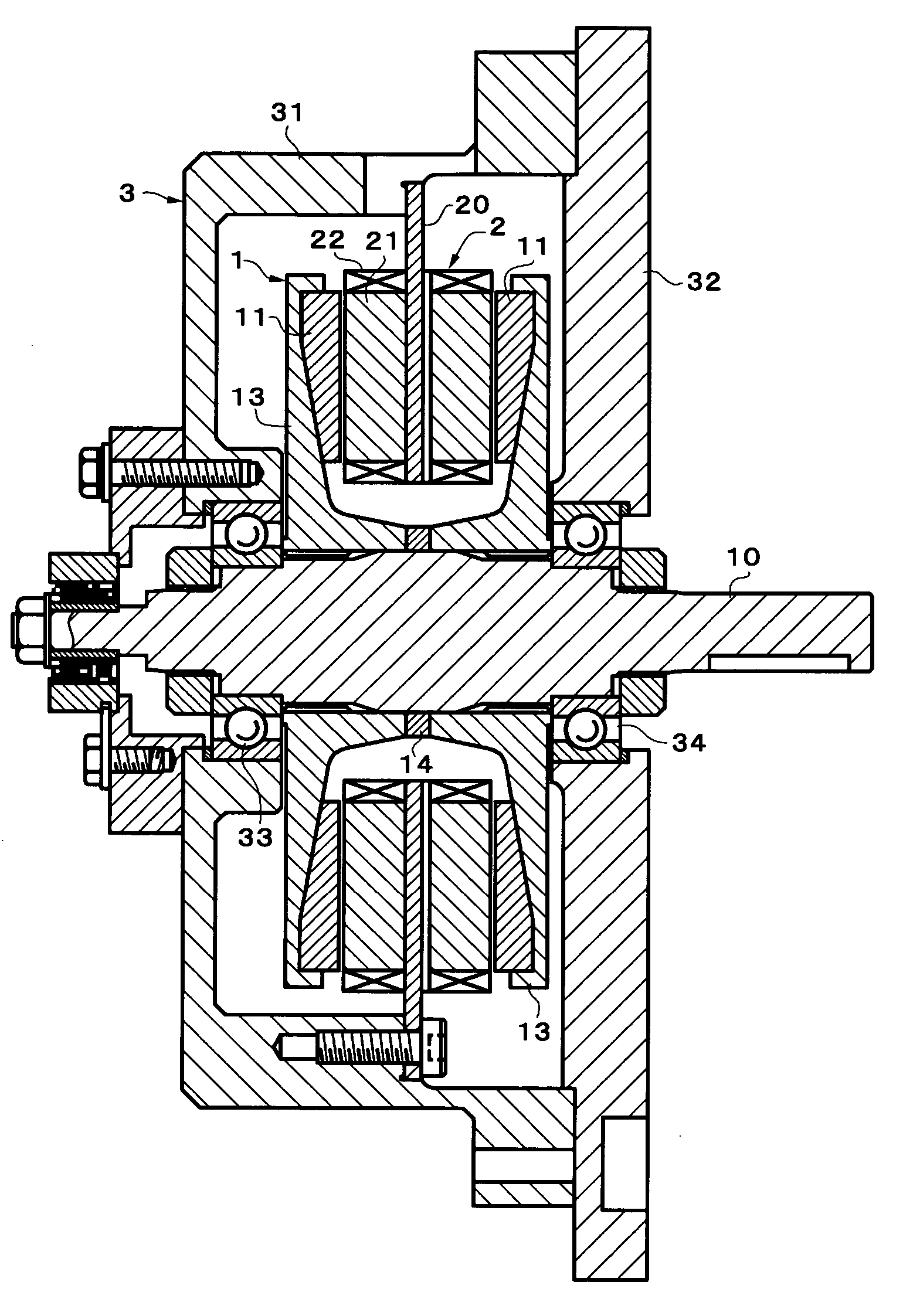
Axial gap rotating electrical machine
a rotating electrical machine and axial gap technology, applied in the direction of dynamo-electric machines, dynamo-electric components, magnetic circuit shapes/forms/construction, etc., can solve the problems of uneven magnetic path at the outer periphery and inner periphery, insufficient magnetic force of permanent magnets in the torque, and too large magnetic flux density on the inner circumferential side, so as to prevent magnetic saturation of the core. , the effect of improving the torque outpu
- Summary
- Abstract
- Description
- Claims
- Application Information
AI Technical Summary
Benefits of technology
Problems solved by technology
Method used
Image
Examples
first embodiment
[First Embodiment]
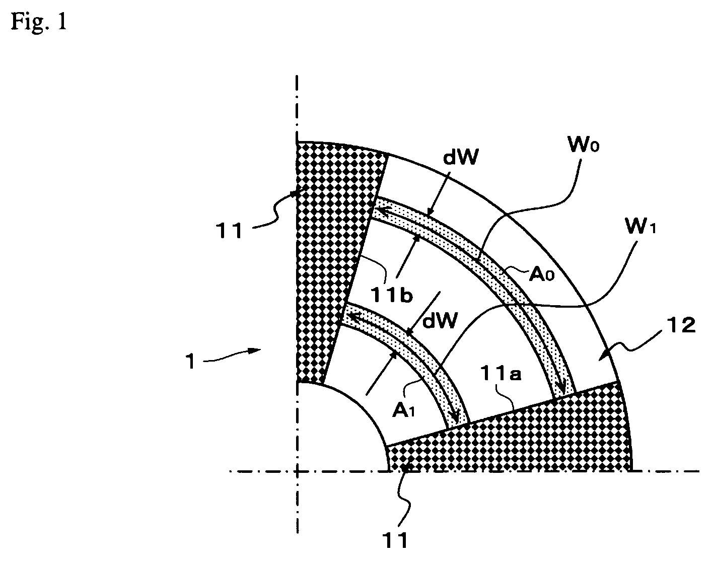
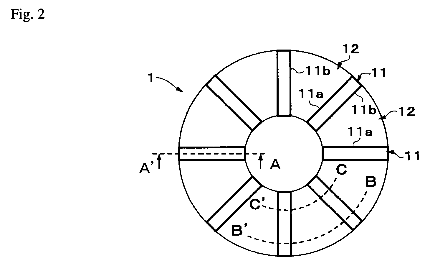
[0045]Exemplary embodiments of the present invention will hereinafter be described with reference to the appended drawings. FIGS. 2 to 4 show a first exemplary embodiment. This exemplary embodiment realizes a structure in which the amount of magnetic flux on the outside in the radial direction of a rotor 1 is made greater than the amount of magnetic flux on the inside in the radial direction by making the sectional area (S) per unit length (i.e., the dW), in the radial direction of the rotor, of permanent magnets (hereinafter simply referred to as “magnets” in the embodiments) 11 larger at the outer circumferential side than it is at the inner circumferential side. More specifically, the magnets 11 in this exemplary embodiment are made thinner, when viewed in the axial direction of the rotor 1 (i.e., the direction perpendicular to the paper on which the drawing is drawn), on the inner radial side of the rotor than they are on the outer radial side of the rotor.
[004...
second embodiment
[Second Embodiment]
[0060]Next, a second exemplary embodiment shown with reference to FIGS. 8 and 9 realizes a structure in which the amount of magnetic flux on the outside in the radial direction of the rotor 1 is made larger than the amount of magnetic flux on the inside in the radial direction by making a magnetomotive force (F) in each position, in the radial direction of the rotor, of the magnets 11 greater at the outer circumferential side of the rotor than it is at the inner circumferential side of the rotor. More specifically, the magnets 11 in this example are structured so that their widths, when viewed from the circumferential direction of the rotor 1, are made smaller on the inner radial side of the rotor than they are on the outer radial side of the rotor.
[0061]FIG. 8 is a representational plan view of the rotor as viewed from the side that faces the stator. FIG. 9 is a representational sectional view of cross-sections taken across lines D–D′ and E–E′ of FIG. 8. All of t...
third embodiment
[Third Embodiment]
[0069]Next, a third exemplary embodiment shown with reference to FIG. 10 realizes a structure in which the amount of magnetic flux at the outside in the radial direction of the rotor 1 is made larger than the amount of magnetic flux at the inside in the radial direction of the rotor 1 by making the magnetic flux density (B), in the radial direction of the rotor, at the magnetization surfaces of the magnets greater on the outer radial side than it is on the inner radial side. More specifically, the magnets 11 in this example are structured such that the amount of magnetization in the radial direction of the rotor is less on the inner radial side than it is on the outer radial side.
[0070]FIG. 10 is a representational sectional view showing the rotating electrical machine cut at the same portions as the cross-sections taken along lines B–B′ and C–C′ in the representational plan view (FIG. 2) of the first exemplary embodiment (in this example, the cross-sections are de...
PUM
 Abstract
Description
Claims
Application Information
 - R&D
- Intellectual Property
- Life Sciences
- Materials
- Tech Scout
- Unparalleled Data Quality
- Higher Quality Content
- 60% Fewer Hallucinations
Browse by: Latest US Patents, China's latest patents, Technical Efficacy Thesaurus, Application Domain, Technology Topic, Popular Technical Reports.
© 2025 PatSnap. All rights reserved.Legal|Privacy policy|Modern Slavery Act Transparency Statement|Sitemap|About US| Contact US: help@patsnap.com


