Digital micromirror device with simplified drive electronics for use as temporal light modulator

a digital micromirror and temporal light technology, applied in the field of digital micromirror devices, can solve the problems of complex drive electronics of dmd, which are not needed for this type of application, and achieve the effect of reducing the cost of operation

a digital micromirror and temporal light technology, applied in the field of digital micromirror devices, can solve the problems of complex drive electronics of dmd, which are not needed for this type of application, and achieve the effect of reducing the cost of operation

US7187484B2Inactive Publication Date: 2007-03-06TEXAS INSTR INC

Image

  • Digital micromirror device with simplified drive electronics for use as temporal light modulator
  • Digital micromirror device with simplified drive electronics for use as temporal light modulator
  • Digital micromirror device with simplified drive electronics for use as temporal light modulator

Examples


Embodiment Construction

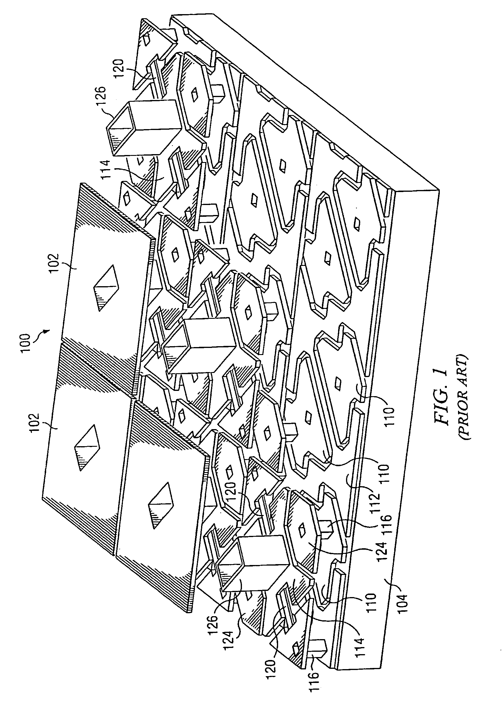
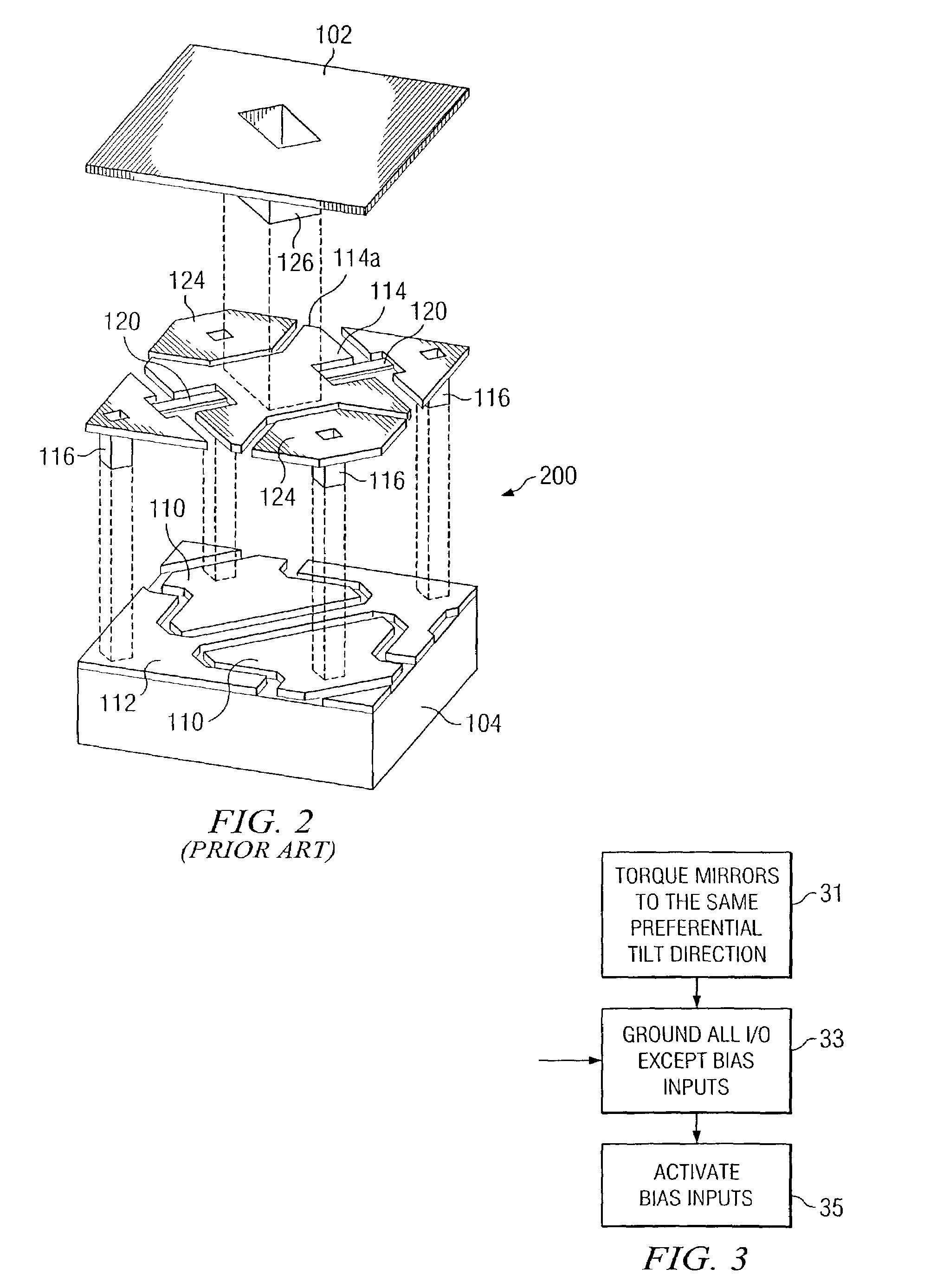
[0016]The following description is directed to two applications of the DMD as a temporal intensity modulator for a light source such as a laser. It should be understood that although the following description is directed to the DMD manufactured by Texas Instruments Incorporated, the same concepts could apply to other micromirror devices having mirror arrays and addressing circuitry that could be modified in the manner described herein.

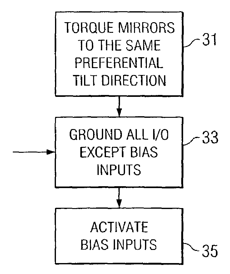
[0017]A first application is as a chopper-type light modulator. For this application, the DMD is operated in a digital mode, in the sense that the mirrors cycle between a fully landed (“all on” or “all off”) state and a flat state. For a second application, the DMD is operated in an analog mode, such as for optical equalizer or heterodyne applications. For this application, the mirrors are not landed. Rather, an analog voltage, whose magnitude is insufficient to land the mirrors, is applied so as to modulate the tilt angle of the mirror about a chosen ...


PUM


Abstract

A digital micromirror device (DMD) modified for use as a temporal light modulator. The DMD is modified so that the mirrors of the DMD have a preferential tilt direction. The inputs and outputs of the DMD are connected to common ground, except for the bias input lines. The latter are connected to a common excitation input, which is used to cyclically reposition the mirrors between tilted and flat states.

Description

TECHNICAL FIELD OF THE INVENTION[0001]This invention relates to digital micromirror devices, and more particularly to a method of using a digital micromirror device as a temporal light modulator.BACKGROUND OF THE INVENTION[0002]A Digital Micromirror Device™ (DMD™) is a type of microelectromechanical systems (MEMS) device. Invented in the 1980's at Texas Instruments Incorporated, the DMD is a fast, reflective digital light switch.[0003]The DMD has a variety of applications, such as imaging systems and optical switching. For imaging systems, the DMD is combined with image processing, memory, a light source, and optics to form a digital light processing system capable of projecting large, bright, high-contrast color images.[0004]DMD's may have a variety of designs, and the most popular design in current use is a structure consisting of a mirror that is rigidly connected to an underlying yoke. The yoke in turn is connected by two thin, mechanically compliant torsion hinges to support po...

Claims


Application Information

Patent Timeline
06 Mar 2007
Publication
US7187484B2
IPC
G02B26/00; G02B26/08
CPC
G02B26/0841
Inventors
MEHRL, DAVID J.