Timing recovery circuit

a recovery circuit and timing technology, applied in the direction of digital transmission, electrical equipment, synchronising arrangement, etc., can solve the problem of reducing the phase error for a relatively long time period, the difference between the sampling rate of digital signals on the transmission and receiving end, and the inability to accurately estimate the frequency and phase, so as to avoid the steady estimation error of frequency and phase

Active Publication Date: 2007-03-06
VIA TECH INC
View PDF5 Cites 69 Cited by
  • Summary
  • Abstract
  • Description
  • Claims
  • Application Information

AI Technical Summary

Benefits of technology

[0011]The object of the present invention is to provide a timing recovery circuit and a method thereof which avoids a steady estimation error of the frequency and phase resulting from rounding-off imprecision of digital processing.

Problems solved by technology

Further, there is always a difference between the sampling rates of the digital signals on the transmission and receiving ends since the circuitries on these two ends are independent of each other.
Instead, fixed point numbers are typically used, which obviously results in rounding-off imprecision.
Accordingly, in the conventional timing recovery circuit, the phase error increases successively rather than decreases due to the rounding error, which indicates that a relatively long time period is required for reducing the phase error.

Method used


Image

  • Timing recovery circuit
  • Timing recovery circuit
  • Timing recovery circuit

Examples


Embodiment Construction

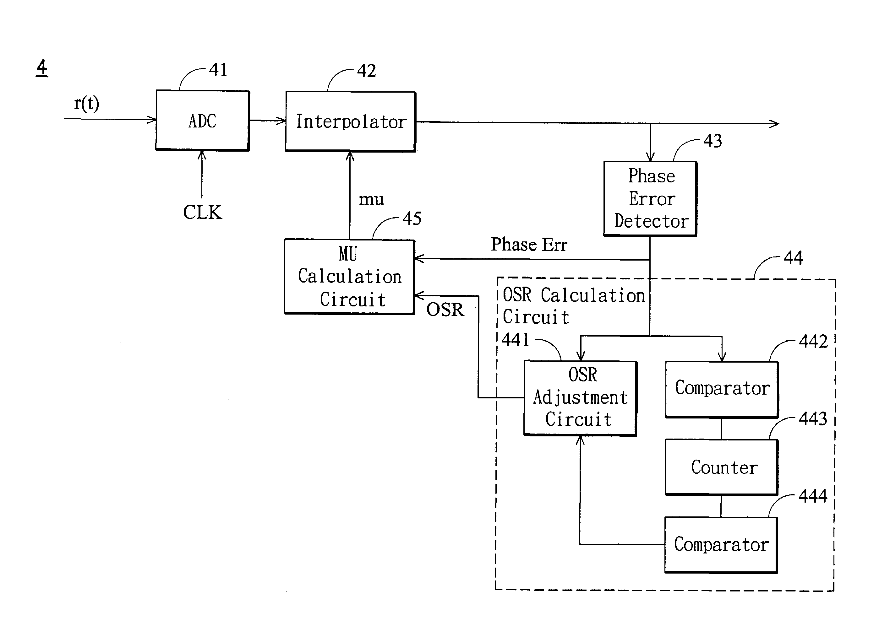
[0020]FIG. 4 is a diagram showing a timing recovery circuit according to one embodiment of the invention. The timing recovery circuit 4 includes an analog-to-digital converter (ADC) 41, an interpolator 42, a phase error detector 43, an over-sampling ratio (OSR) adjustment circuit 44 and a MU calculation circuit 45. The analog-to-digital converter 41 samples a received analog signal r(t) at a sampling rate provided by a clock signal CLK. The digital signal output from the analog-to-digital converter 41 is not synchronized since there is a difference between the symbol rate of the signal r(t) and that of the analog-to-digital converter 41. The interpolator 42 receives the signal output from the ADC 41 and generates interpolating samples for signal synchronization purpose. These interpolating samples are then inserted into the aforementioned asynchronized signal according to a control value MU. The synchronized signal output from the interpolator 42 is fed to the phase error detector 4...


PUM


Abstract

A timing recovery circuit and related method is disclosed. The timing recovery circuit encompasses a converter, an interpolator, a phase error detector, an adjustment circuit, and a calculation circuit. The converter samples an input signal to generate an intermediate signal carrying samples of the input signal, while the interpolator inserts an interpolating sample into the intermediate signal in response to a control value to generate an output signal. The phase error detector outputs a phase error of the output signal. The adjustment circuit updates an over-sampling ratio according to a pair of first and second thresholds, and a counting value adjusted in response to the phase error and a median reference value. Finally, the calculation circuit derives the control value from the updated over-sampling ratio, and transferring the control value to the interpolator.

Description

BACKGROUND OF THE INVENTION[0001]1. Field of the Invention[0002]The present invention relates to a timing recovery circuit, and particularly to a timing recovery circuit and a method thereof which avoids a steady estimation error of the frequency and phase resulting from rounding-off imprecision of digital processing.[0003]2. Description of the Prior Art[0004]There are signals transmitted from a transmission end to a receiving end in digital processing or communication systems. Basically, the signals received on the receiving end must be synchronized with those from the transmission end to eliminate the frequency and phase errors generated in the transmission channel. Further, there is always a difference between the sampling rates of the digital signals on the transmission and receiving ends since the circuitries on these two ends are independent of each other. Therefore, there must be a timing recovery means working on the sampling frequency and phase for signal synchronization.[0...

Claims


Application Information

Patent Timeline
Patent Type & Authority Patents(United States)
IPC IPC(8): H04L7/00H04L7/02
CPCH04L7/0029H04L7/0004
Inventor MA, CHING-WEN
Owner VIA TECH INC
Why Eureka
Try Eureka