Boundary scan analysis

a technology of description language and boundary scan, applied in the direction of testing circuits, resistance/reactance/impedence, instruments, etc., can solve the problems of increasing complexity and expense of electronic circuits, increasing the difficulty of accessing certain elements of electronic circuits, and increasing the complexity of electronic circuits

a technology of description language and boundary scan, applied in the direction of testing circuits, resistance/reactance/impedence, instruments, etc., can solve the problems of increasing complexity and expense of electronic circuits, increasing the difficulty of accessing certain elements of electronic circuits, and increasing the complexity of electronic circuits

US7188043B1Active Publication Date: 2007-03-06XILINX INC

Image

  • Boundary scan analysis
  • Boundary scan analysis
  • Boundary scan analysis

Examples


Embodiment Construction

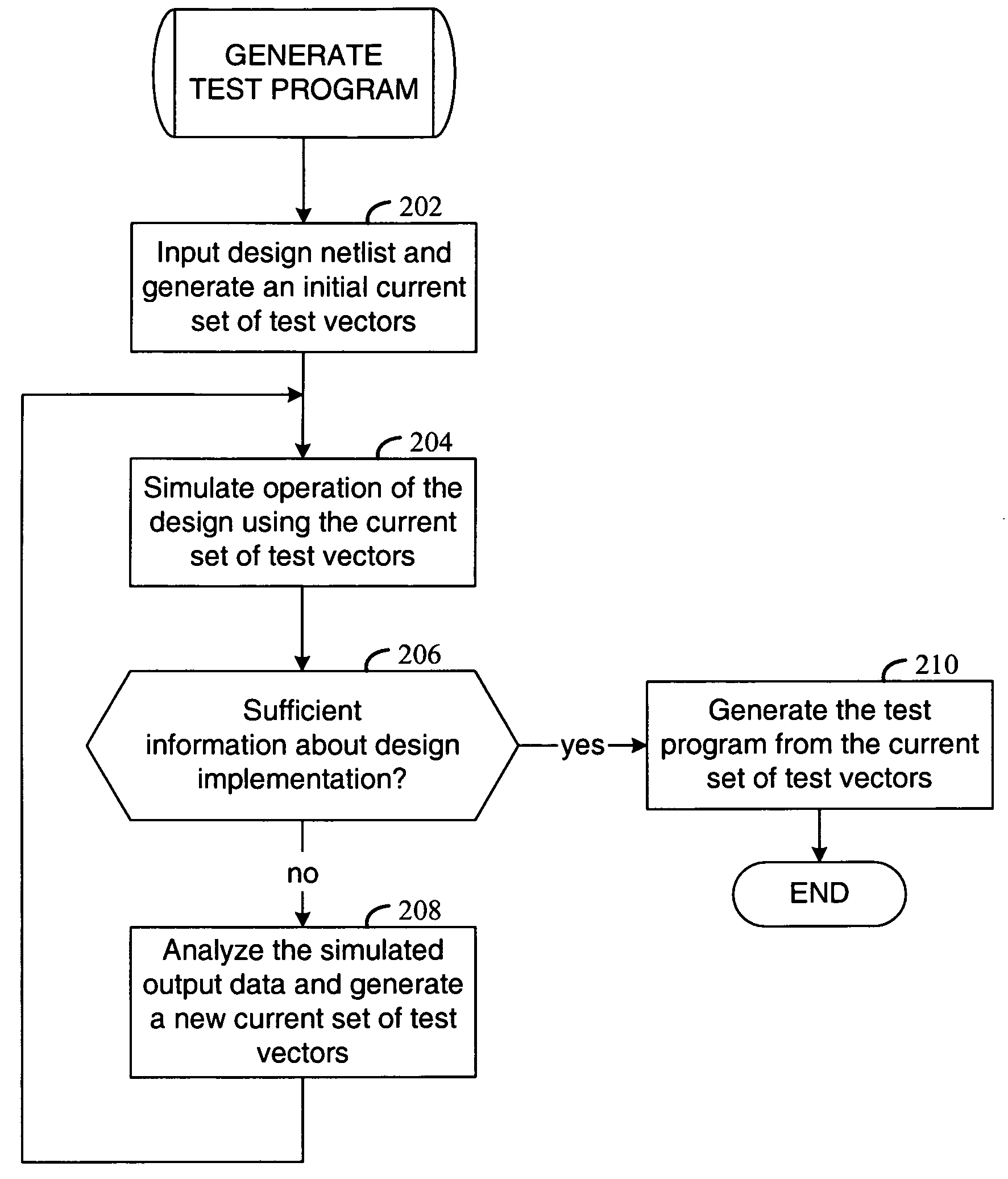
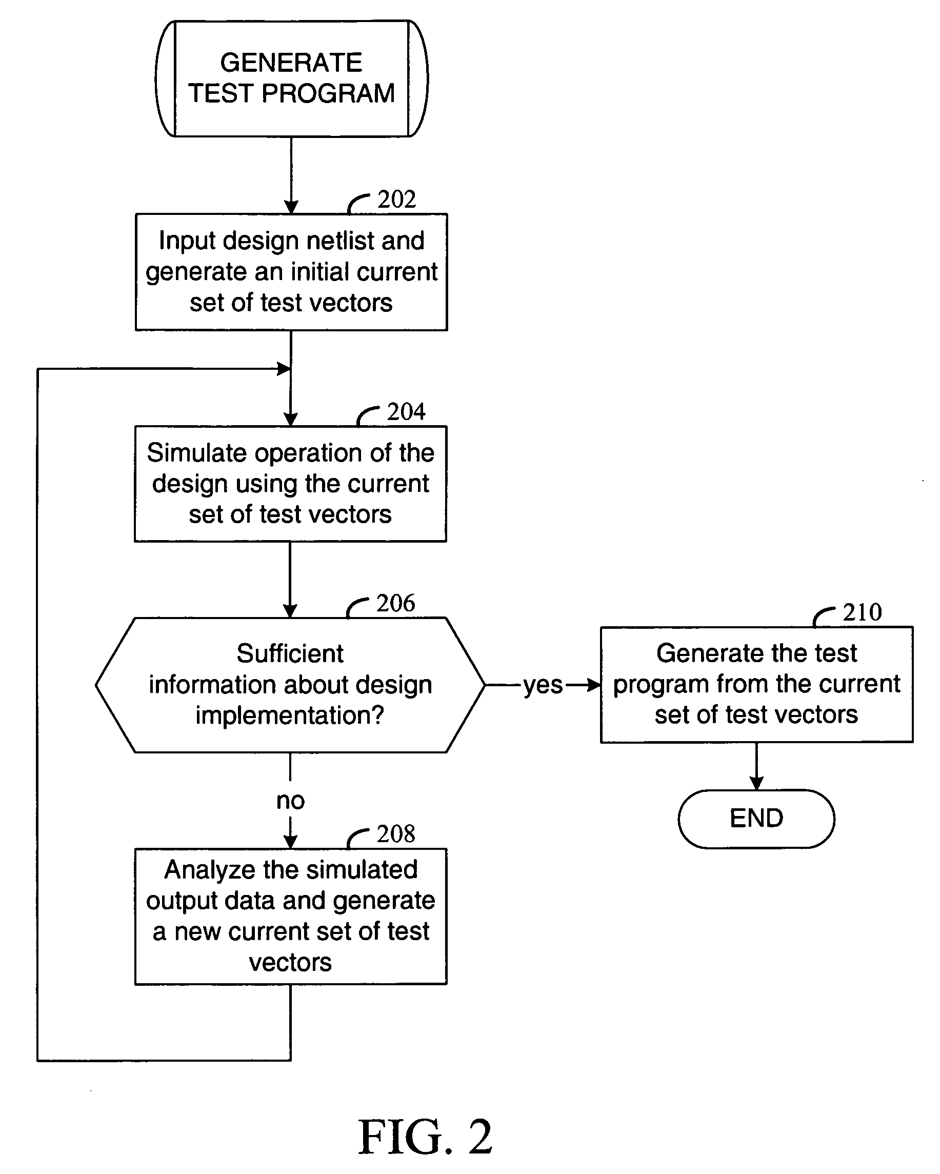
[0018]The present invention is believed to be applicable to a variety of different circuit analysis approaches and implementations, some of which are described herein. Those skilled in the art will appreciate that various aspects of the invention could also apply to a variety of other circuits and testing approaches.

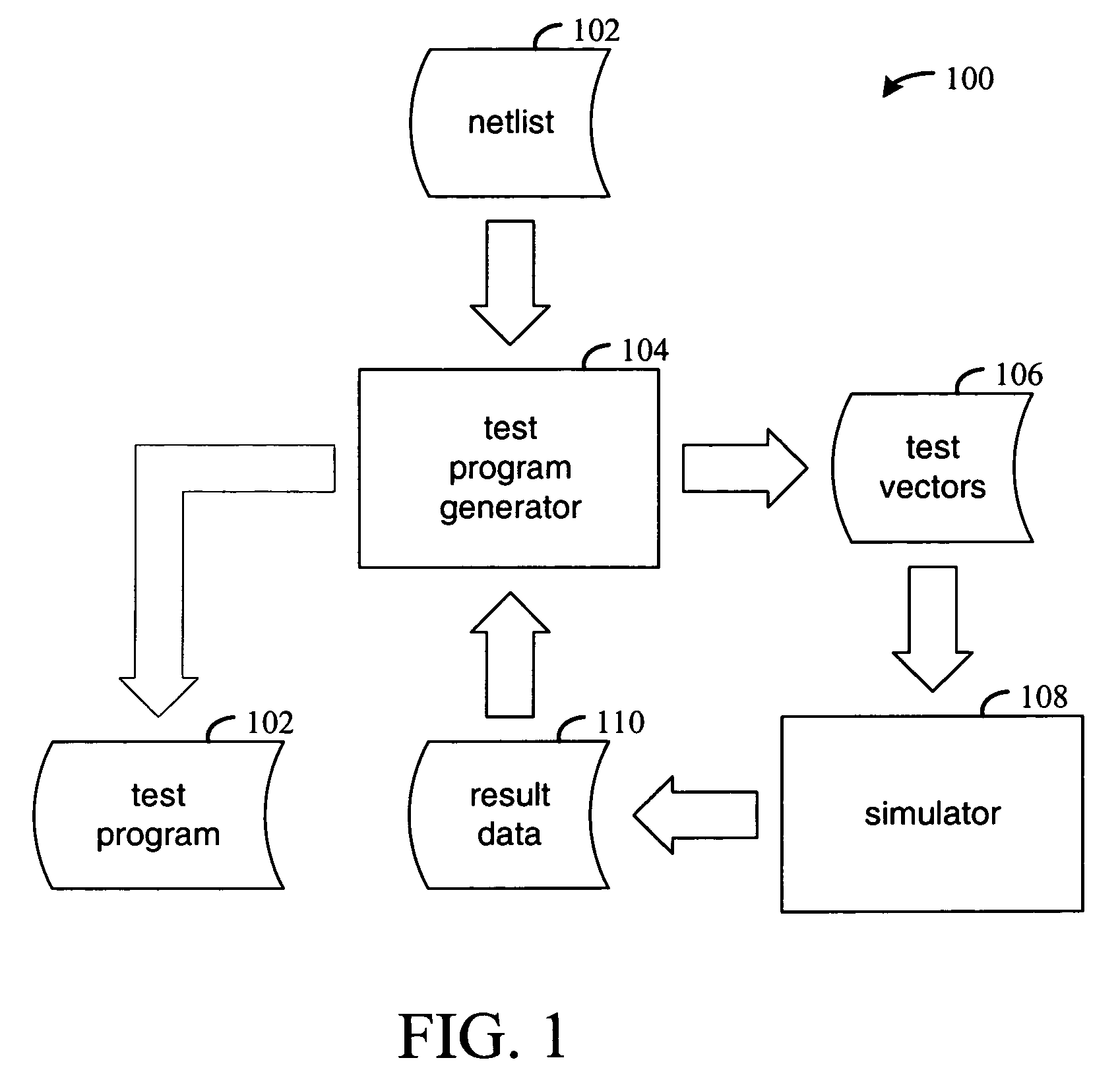
[0019]According to an example embodiment of the present invention, specific characteristics of an electronic circuit used to generate BSDL files are detected using a boundary scan test vector simulation created from a general design schematic of the circuit. Responses (outputs) of the circuit to the test vector simulation are detected and used to identify specific features of the circuit that vary from the general design schematic. For instance, by monitoring output pins of the circuit, a response of the circuit can be mapped to input signals applied to boundary scan chain cells. Circuit paths, schematic net arrangements and other characteristics of the circuit can thus ...


PUM


Abstract

A circuit testing approach involves the generation of boundary scan information using test vectors to identify characteristics of a circuit design and a boundary scan implementation therefor. According to an example embodiment of the present invention, test vectors are used in simulation to identify circuit design characteristics for establishing a boundary scan test program. The test vectors are generated using a netlist of the circuit design. The test vectors are used to simulate operation of the circuit, and responses to the simulation are detected and used to identify design-specific circuit characteristics and a boundary scan test program is generated using the design-specific circuit characteristics.

Description

FIELD OF THE INVENTION[0001]The present invention generally relates to the generation of boundary scan description language (BSDL)-type files using circuit analysis, and more particularly to the analysis of boundary scan chain implementations.BACKGROUND[0002]The demand for high-speed, reliable electronic circuits and devices continues to grow at a rapid pace. Concurrently, the complexity of these circuits has also been increasing to meet the needs of a variety of applications. As the complexity and expense of these electronic circuits increases, the testing and analysis of the circuits for a variety of implementations also becomes increasingly important. In addition, accessing certain elements of these circuits has also become more difficult as the elements themselves are scaled smaller and as circuits are formed in increasingly dense arrangements.[0003]Boundary scan analysis is one type of approach used for testing and analyzing circuits, and has been found particularly useful for ...

Claims


Application Information

Patent Timeline
06 Mar 2007
Publication
US7188043B1
IPC
G01R31/14
CPC
G01R31/318378; G01R31/318544; G01R31/318536
Inventors
WOLF, MIKHAIL A.