
Adaptive memory compression

a memory compression and memory technology, applied in the field of computer memory architectures, can solve the problems of high performance computing, high memory consumption, and high memory consumption, and achieve the effect of increasing the data block

Inactive Publication Date: 2007-03-06
INT BUSINESS MASCH CORP
View PDF5 Cites 32 Cited by
  • Summary
  • Abstract
  • Description
  • Claims
  • Application Information

AI Technical Summary

Problems solved by technology

Computer memory systems have at least two major problems: there is seldom enough memory and what memory there is tends to be expensive.
Unfortunately, high performance computing, e.g. computer gaming, demands large amounts of fast memory.
Memory is often the most expensive component of many computer architectures.
Historically, compression was not been widely used because of difficulties associated with memory space management.
High performance computing represents an additional problem since the latency problems associated with compressing and uncompressing data must be overcome.
That is, before compressed data can be used it must be uncompressed, which takes time, and then that data must be recompressed, which takes additional time, before storing.
In some applications latency concerns are so severe that data compression historically could not be used.
While in most cases an assumed minimum compression ratio is practical, some data simply does not compress well.
In fact, some data compresses very little, if at all.
Unfortunately, in high performance computing such huge amounts of similar data must be processed that when poorly compressed data does occur; there can be a lot of it.
So, when poorly compressed data does occur the system memory is in danger of filling up.
If the memory fills, data can be lost or data must be offloaded from memory (e.g., to a hard drive or “disk”), often resulting in a significant drop in system performance.
However, in applications such as computer gaming such approaches are usually unacceptable.
Storing to disk dramatically increases latency issues while dumping a previous display is not a desirable option, as the display will very likely be required again.

Method used


Image

  • Adaptive memory compression
  • Adaptive memory compression
  • Adaptive memory compression

Examples


Embodiment Construction

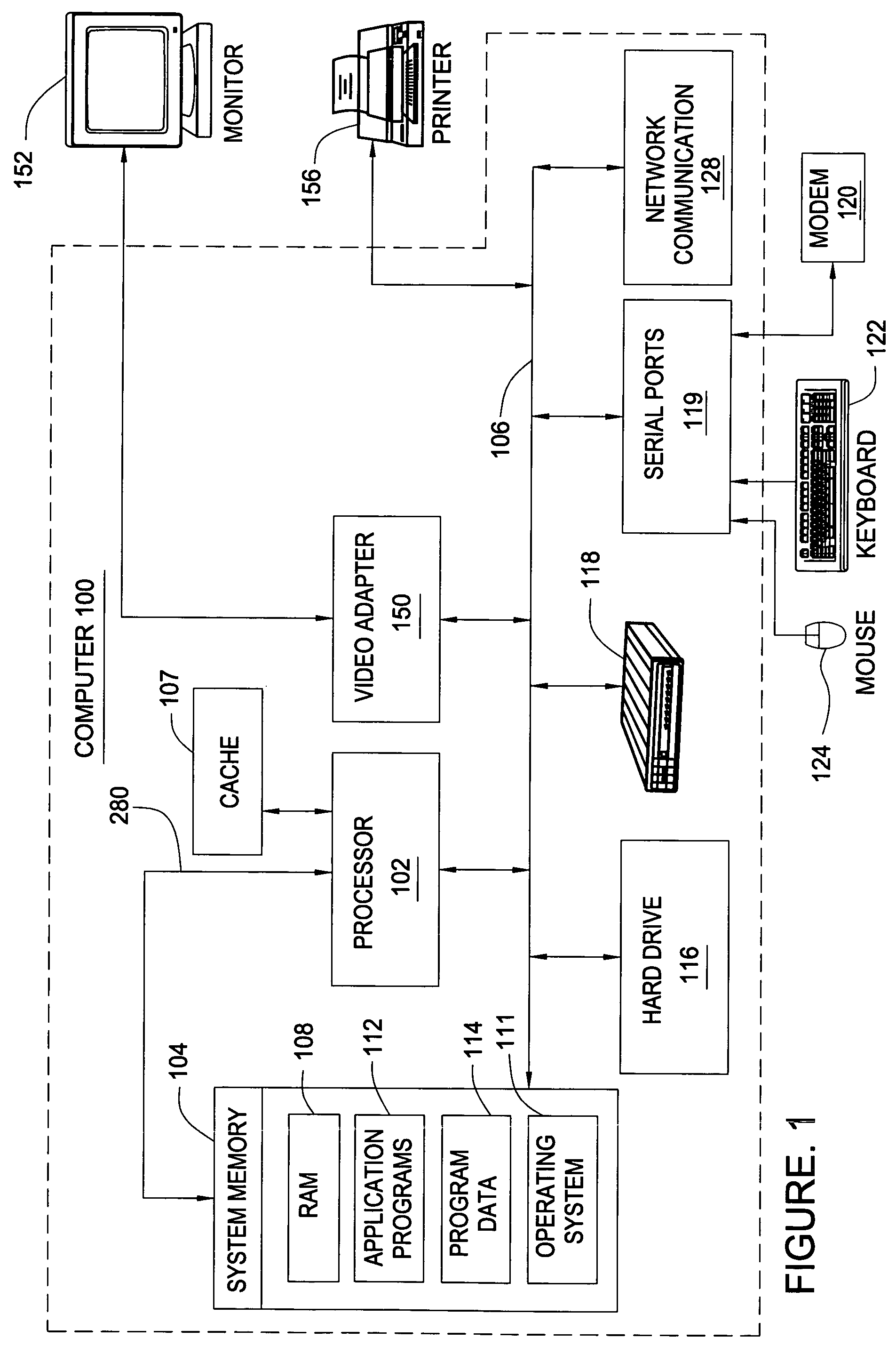
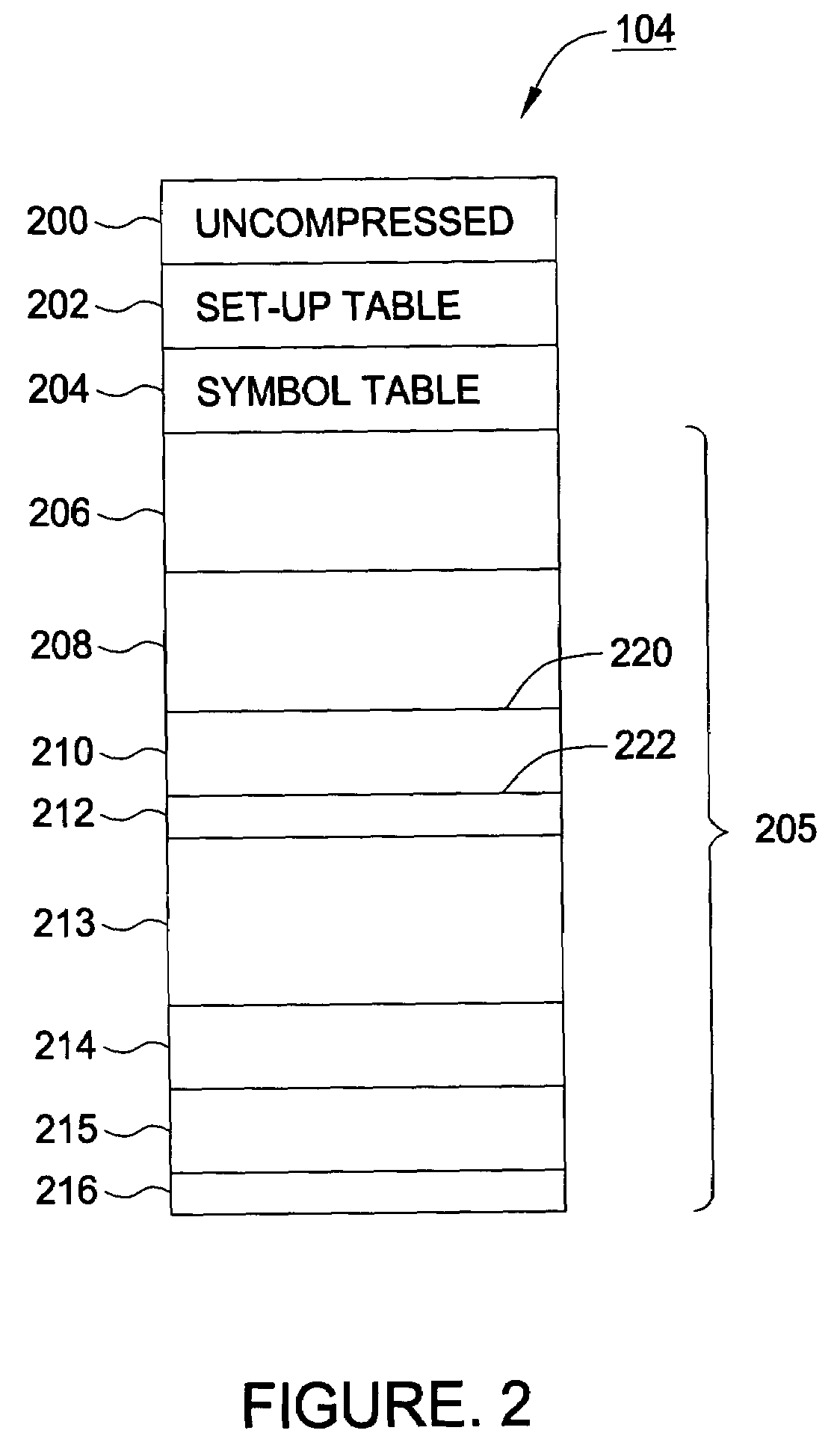
[0026]The present invention provides for a memory architecture in which frequently accessed data is stored in an uncompressed format in a high speed cache to reduce latency. When the data is not being accessed, it is compressed and stored in a main memory store (system memory). In an effort to maintain an expected level of compression, one or more compression parameters are adapted based on a dynamic compression ratio generated from one or more actual achieved compression ratios. For some embodiments, the dynamic compression ratio may be monitored in hardware and, if it falls below a specified threshold level, the hardware generates a trap to software, allowing the software to intelligently modify compression parameters based on system parameters, such as currently running tasks, the amount of available memory remaining, and the like.

[0027]FIG. 1 illustrates a computer 100 that incorporates the principles of the present invention. The computer 100 may represent a wide variety of com...


PUM


Abstract

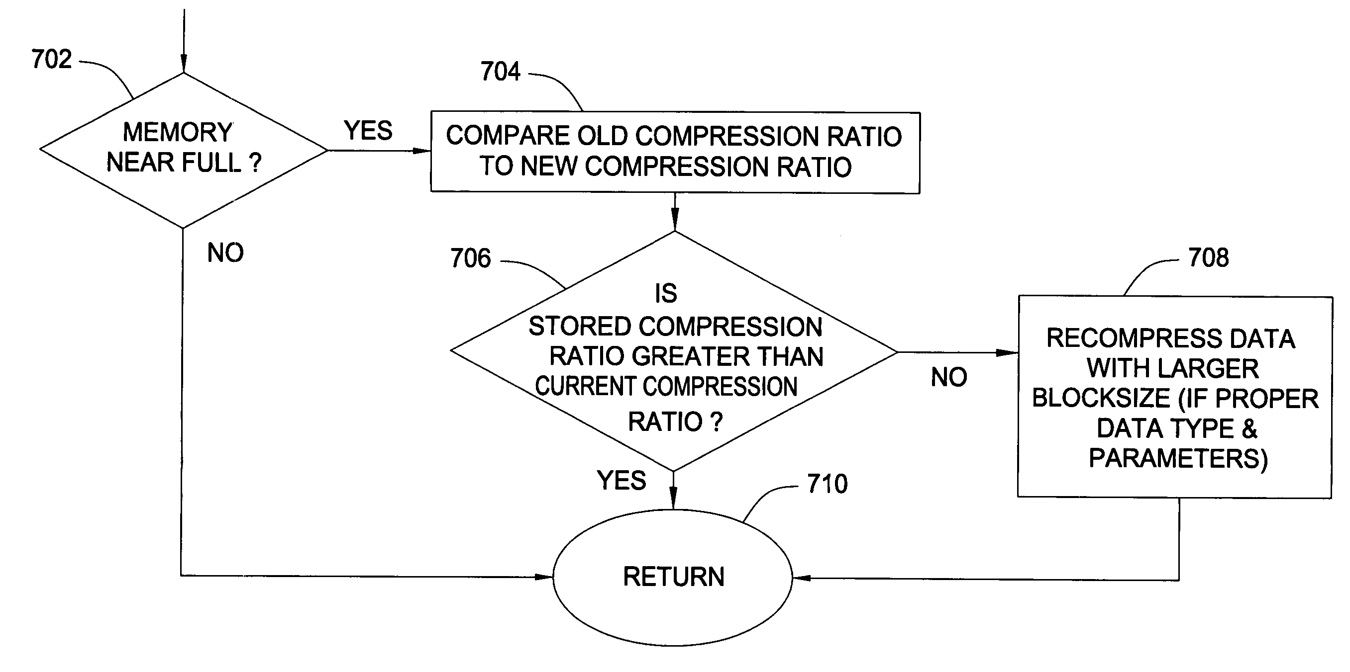
Compressed memory systems and methods that reduce problems of memory overflow and data loss. A compression engine compresses blocks of data for storage in a compressed memory. A compression monitor monitors the achieved compression ratio and provides a software trap when the achieved compression ratio falls below a minimum. After the trap is provided software monitors the fill state of the compressed memory. If the compressed memory is approaching full, the software changes the block size to improve the compression ratio.

Description

CROSS-REFERENCE TO RELATED APPLICATIONSField of the Invention[0001]The present application is related to commonly-owned U.S. Pat. No. 5,812,817, entitled “Compression Architecture for System Memory Application” and commonly owned co-pending application, entitled “Automatic Temporary Precision Reduction For Enhanced Compression,” filed herewith Ser. No. 10 / 675,427, which are herein incorporated by reference.BACKGROUND OF THE INVENTION[0002]1. Field of the Invention[0003]The present invention relates to computer memory architectures and, more particularly, to maintaining an amount of available memory using adaptive compression techniques.[0004]2. Description of the Related Art[0005]Computer memory systems have at least two major problems: there is seldom enough memory and what memory there is tends to be expensive. Unfortunately, high performance computing, e.g. computer gaming, demands large amounts of fast memory. Memory is often the most expensive component of many computer archite...

Claims


Application Information

Patent Timeline
Patent Type & Authority Patents(United States)
IPC IPC(8): G06F12/06G06F12/00G06F12/04G06F12/08
CPCG06F12/04G06F12/0802G06F2212/401
Inventor LUICK, DAVID A.
Owner INT BUSINESS MASCH CORP
Learn More