Screening device, such as a screen cylinder, and method of manufacture of the screening device

a screening device and screen cylinder technology, applied in the direction of screening, stationary filtering element filtering, screening, etc., can solve the problems of variable distortion, thermal stress and burr, change in the opening width of the screening device between adjacent wires, etc., and achieve the effect of small width and good toleran

Inactive Publication Date: 2007-03-13
AIKAWA FIBER TECH
View PDF17 Cites 11 Cited by
  • Summary
  • Abstract
  • Description
  • Claims
  • Application Information

AI Technical Summary

Benefits of technology

[0035]The present invention is applicable in screen cylinders having inward or outward flow of suspension to be screened. In inward flow screens screen wires are connected to the external surface of supporting plates or cylinders and in outward flow to the inner surface of the plates or cylinders respectively. The present invention provides a substantially improved screening device and method of manufacturing and assembling such a device. The invention particularly provides an improved method of manufacturing a screening device, so that accurate and uniform screening slots, i.e., good tolerance, with very small widths may be manufactured. The new screening device provides a method of manufacturing a strong screening device with a minimum of burrs or other protruding elements causing accumulation of fibers.

Problems solved by technology

The screen wires are generally fastened to the supporting elements by a welding process which gives rise to a number of disadvantages such as variability distortion, thermal stresses and burrs.
The heat induced by the welding often cause distortion of the wires and changes in the screening opening width between adjacent wires.
It is therefore difficult to get completely uniform screening openings, which means that the efficiency of the screen suffers.
The thermal stresses and the burrs may also lead to failure in operation due to the loading on the screening device in the user's process.
Such loading may be either in the form of a constant load or a cyclic loading giving rise to failure by fatigue.
Burrs may also catch fibers in the suspension, leading to gradual clogging of the screen or filter, or the formation of so called “strings,” which are very detrimental in the user's process.
This design, thereby, requires the manufacturing of a number of relatively complicated and therefore expensive recesses.
Further, it can only be adapted to circular or round screens.
Also the looped areas tend to have cavities and uneven spots which are facing the suspension potentially causing fiber hang-up.
The above difficulties tend to result in poor quality of screening or mechanical weaknesses or to high manufacturing costs.
A further problem concerning ordinary wire screen cylinders, the structure of which is such that the screen wires are supported by circumferential rings, whereby the screen wires carry all the axial loading, is the bending of the screen wires under load.

Method used


Image

  • Screening device, such as a screen cylinder, and method of manufacture of the screening device
  • Screening device, such as a screen cylinder, and method of manufacture of the screening device
  • Screening device, such as a screen cylinder, and method of manufacture of the screening device

Examples


Embodiment Construction

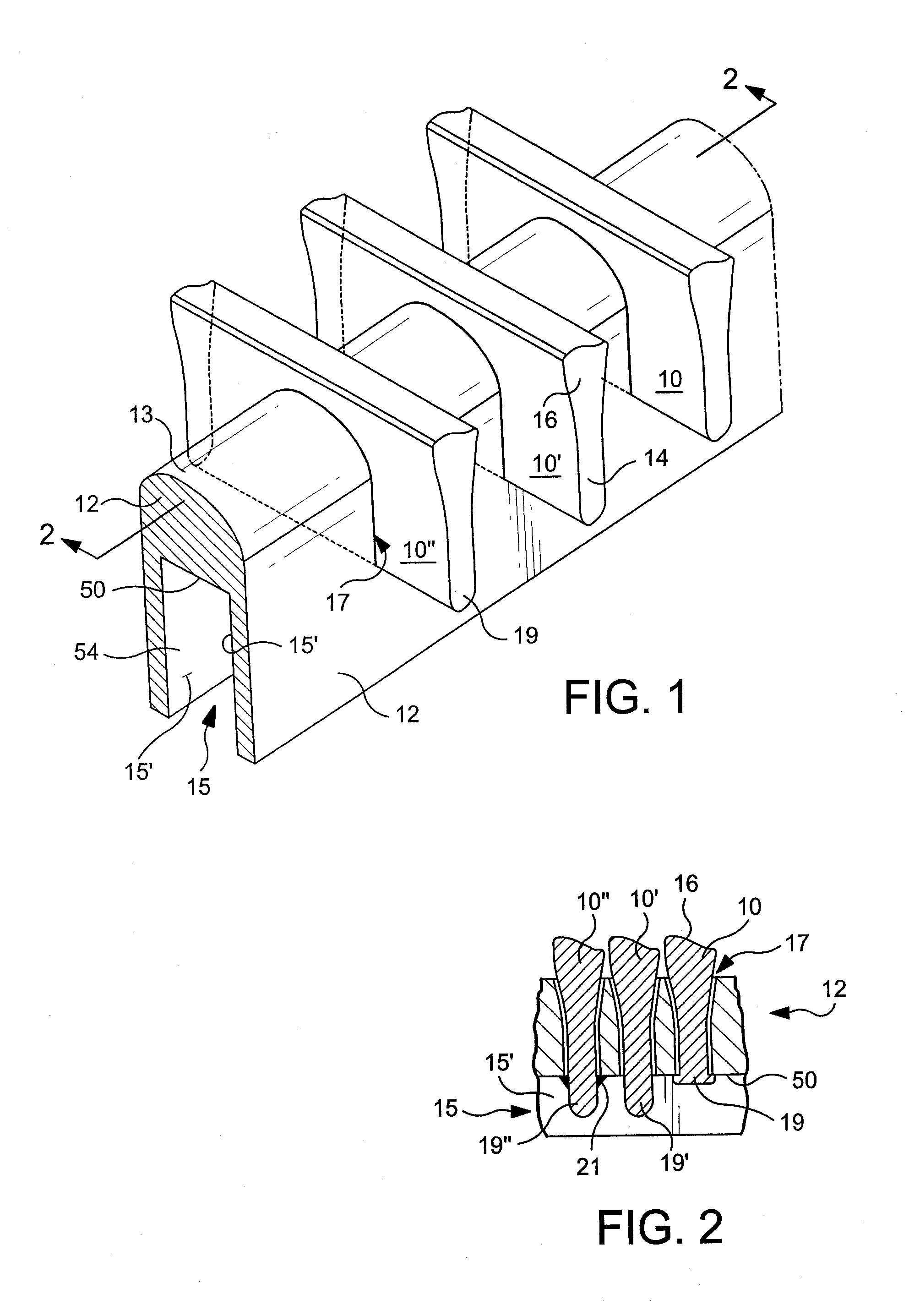
[0051]FIG. 1 shows schematically a top / side view of a portion of a screening device according to a preferred embodiment of the present invention. In FIG. 1, three filter wires 10, 10′ and 10″ are positioned onto a partly solid support bar 12, having an elongated cross section with a rounded top part 13, facing accept flow, and a bottom part with a cavity 15, having side walls 15′, therein.

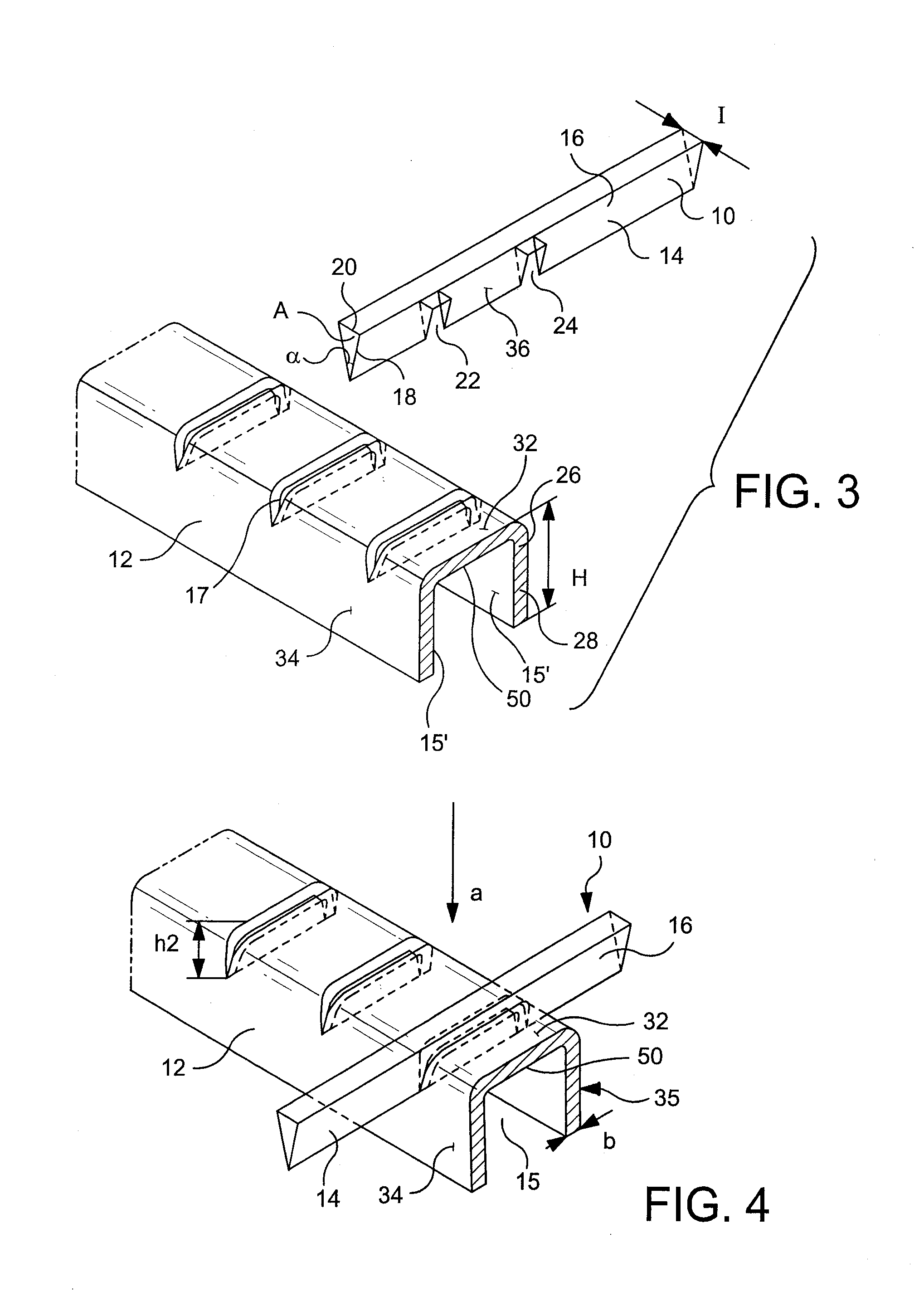
[0052]The filter wires 10, 10′,10″ have narrow lower parts 14, i.e., down-stream portions, and funnel shaped upward widening top parts 16, i.e., upstream portions. The wires are mounted onto the support bar by inserting the narrow lower parts 14 in slots 17 formed through the top or upstream side of the support bar 12. The slots 17 are substantially perpendicular to the longitudinal axis of the support bar 12. The slots 17 are also substantially perpendicular to the top surface of the support bar, for the filter wires to reach radially outward from the support bar.

[0053]The bottom edges 19 of the f...


PUM

PropertyMeasurementUnit
thicknessaaaaaaaaaa
widthaaaaaaaaaa
widthaaaaaaaaaa

Abstract

A screening device (e.g., screen plate or screen cylinder) is manufactured relatively inexpensively and easily yet has uniform screening openings (e.g., screening slots) even when of a width of less than 0.5 mm. A plurality of wires having first and second sections (the second sections having base portions and of smaller cross-section than the first sections) are mounted substantially parallel to each other, supported by at least one support bar or ring. The bars or rings have slots formed in a first side surface, and a cavity in open communication with the slots in a second side surface. The wires are fixed to the bars or rings by deforming the wires (e.g., by bending a flap, engagement by a reciprocating tool, welding, etc.) within the cavity, or by deformation of the support bar or ring in the cavity. The screen plate or cylinder is preferably used to screen or otherwise treat a cellulose pulp suspension, e.g., by subjecting the first sections of the wires to a flow of pulp with accepts passing through the screening openings.

Description

CROSS-REFERENCES TO RELATED APPLICATIONS[0001]This is a continuation-in-part of U.S. patent application Ser. No. 10 / 143,763, filed May 14, 2002, now abandoned; which is a divisional of U.S. patent application Ser. No. 09 / 269,904, filed Aug. 19, 1999, now U.S. Pat. No. 6,426,003; which claims priority of PCT / FI96 / 00520, filed Oct. 3, 1996, the entire contents of which are hereby incorporated by reference in this application.STATEMENT REGARDING FEDERALLY SPONSORED RESEARCH OR DEVELOPMENT[0002](NOT APPLICABLE)BACKGROUND OF THE INVENTION[0003]The present invention refers to a screening device and a method of manufacture thereof as recited in the preamble of appended independent claims. The present invention thereby refers to screening devices, such as screen cylinders or bent or flat screening elements, for screening, filtrating, fractioning or sorting pulp suspensions in pulp and paper making industry or other similar suspensions. The present invention more particularly refers to scree...

Claims


Application Information

Patent Timeline
Patent Type & Authority Patents(United States)
IPC IPC(8): B01D29/44B01D29/11B01D33/00B07B1/18B07B1/46D21D5/16
CPCB01D29/111B01D33/0093B07B1/18B07B1/4618B07B1/4681D21D5/16B01D29/445B01D33/067B01D33/275Y10T29/49604
Inventor MAY, JONATHAN P.WOOD, TIMSTEPHENSON, JOHNJURVANEN, JARIPUTKONEN, JAAKKO
Owner AIKAWA FIBER TECH
Why Eureka
Try Eureka