Light guide plate and support unit for the same

a technology of support unit and light guide plate, which is applied in the direction of lighting and heating apparatus, instruments, machines/engines, etc., can solve the problems of reducing the thickness of the backlight device, increasing not only the number of parts and the cost, but also the number of manufacturing steps due,

Active Publication Date: 2007-03-13
CITIZEN ELECTRONICS CO LTD
View PDF14 Cites 97 Cited by
  • Summary
  • Abstract
  • Description
  • Claims
  • Application Information

AI Technical Summary

Benefits of technology

[0020]The clamp portion may comprise a transparent resin material or a transparent resin material containing a fluorescent material to allow light from the light emitting element to enter the light receiving surface of the light guide...

Problems solved by technology

This construction in which the thin light guide plate receives light from its side, however, results in a poor light receiving efficiency.
In a backlight structure such as disclosed in the above official gazette, however, a separate condenser lens needs to be installed in the device, which increases not only the number of parts a...

Method used


Image

  • Light guide plate and support unit for the same
  • Light guide plate and support unit for the same
  • Light guide plate and support unit for the same

Examples


first embodiment

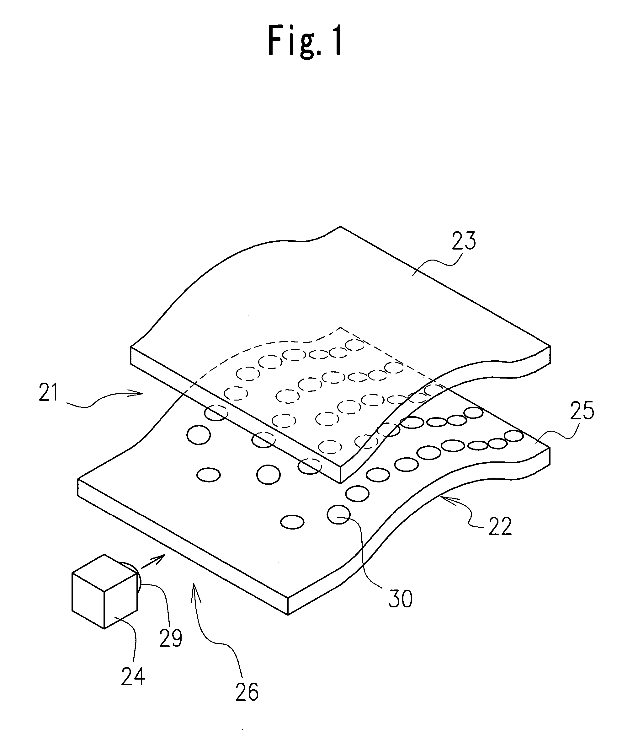
[0036]FIG. 1 shows a construction of a display 21 having a light guide plate 22 according to the invention. The display 21 comprises a liquid crystal panel 23 as a display body, a light guide plate 22 arranged on the back side of the liquid crystal panel 23, and a light source (LED 24) arranged close to one side surface of the light guide plate 22.

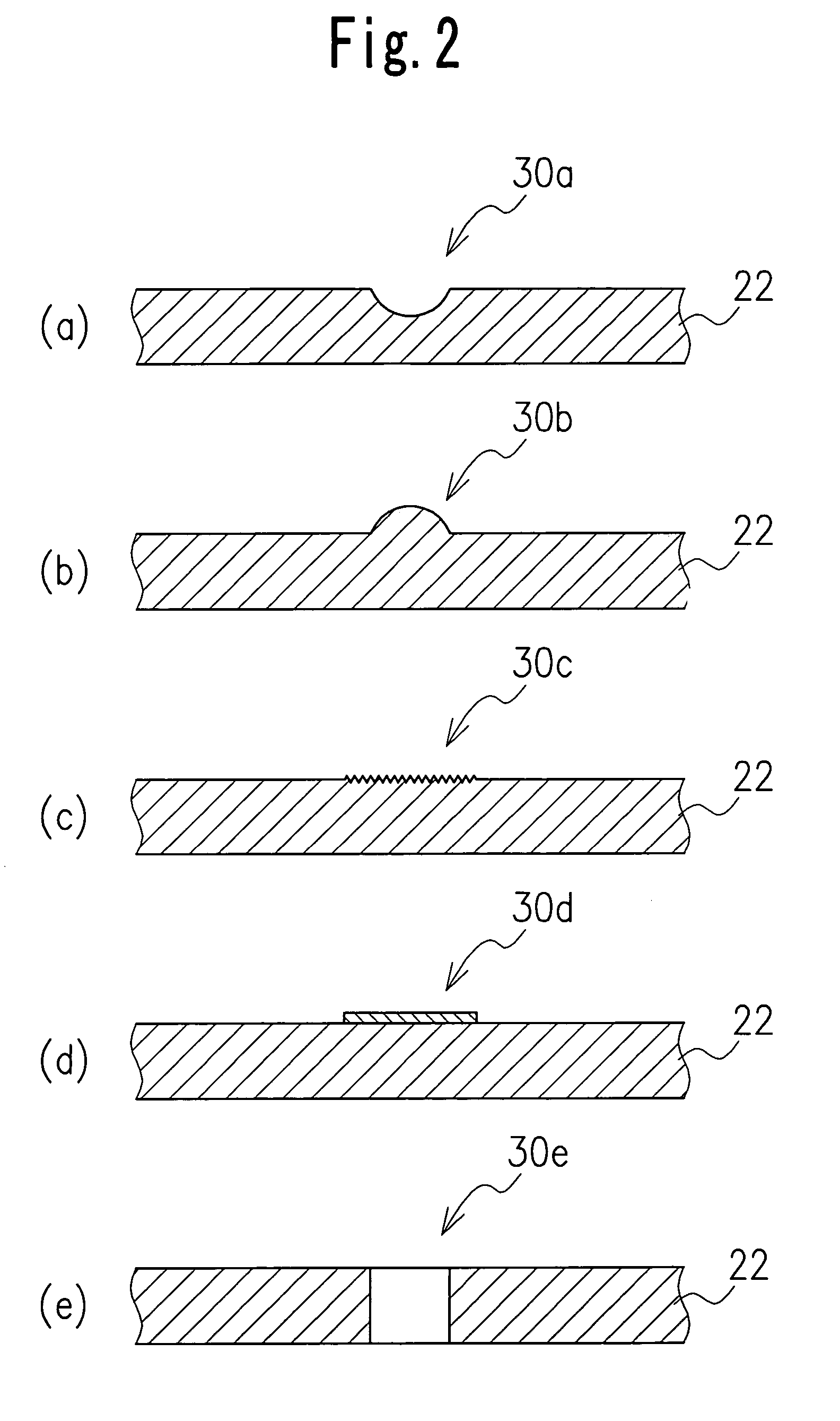
[0037]The liquid crystal panel 23 has a curved surface conforming to the shape of an electronic device on which it is mounted. The light guide plate 22 is also curved to match that shape. The light guide plate 22 comprises for example a flexible, transparent or translucent sheet member, such as polyethylene terephthalate (PET), silicone or polyimide, about 0.1 mm thick and is bendable into any desired shape. The light guide body 25 forming the light guide plate 22 has formed on its upper surface facing the liquid crystal panel 23 a plurality of light scattering portions 30 to scatter light toward the liquid crystal panel 23.

[0038]In the di...

fourth embodiment

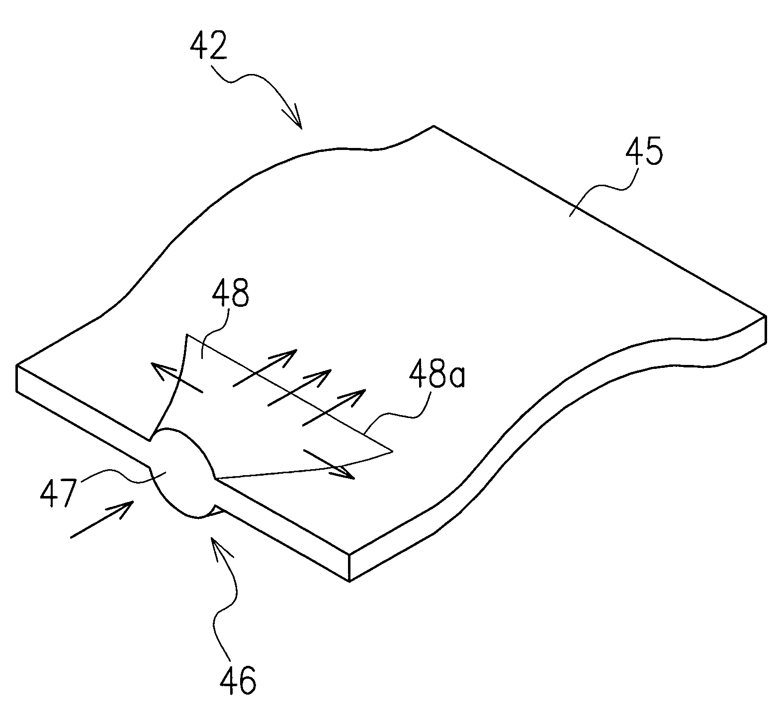
[0047]FIG. 7 shows a light guide plate 52 according to this invention. As shown in the figure, a light receiving portion 56 of the light guide plate 52 has an enlarged light receiving face 57 of a laterally elongate, oval shape. As in the preceding embodiment, the light receiving portion 56 also has a light introducing portion 58 that expands left and right as it extends from the enlarged light receiving face 57 into a light guide body 55. With this light guide plate 52, since the enlarged light receiving face 57 is horizontally wide, light can effectively be introduced into the light guide body 55 without leakage even when a relatively large LED is used.

fifth embodiment

[0048]FIG. 8 shows a light guide plate 62 according to the invention. As shown in the figure, a light receiving portion 66 of the light guide plate 62 has a rectangular, enlarged light receiving face 67 formed by increasing the thickness of a light guide body 65 at one side surface uniformly over the entire depth. The light receiving portion 66 also has a light introducing portion 68 which is tapered moderately to reduce its thickness toward the light guide body 65. Since the enlarged light receiving face 67 is formed over the entire side surface of the light guide body 65, it is possible to arrange a plurality of LEDs along the enlarged light receiving face 67 or use a barlike fluorescent lamp instead of the LEDs. This configuration is particularly suited where a large quantity of light needs to be taken in. Rays of light, emitted uniformly from a plurality of LEDs or barlike fluorescent lamp and entering the enlarged light receiving face 67 parallel thereto, pass through the light...


PUM


Abstract

The light guide plate 32 has a light receiving portion 36 on one side thereof to receive light emitted by the LED 24 and a flexible light guide body 35 for transforming the light received by the light receiving portion 36 into planar light. The light guide body 35 is arranged along the liquid crystal panel 23 and has a plurality of light scattering portions 30 arranged on an outer surface thereof in a propagation direction of light emitted by the LED 24. Since the light guide plate 32 comprises a flexible member and thus can be arranged in a curved shape conforming to the liquid crystal panel 23 having a curved surface portion, the curved surface portion of the liquid crystal panel 23 can be illuminated uniformly. Further, the provision of the light scattering portions 30 can enhance a light reception efficiency and light emission efficiency even if the light guide plate 32 is thin.

Description

BACKGROUND OF THE INVENTION[0001]1. Field of the Invention[0002]The present invention relates to a light guide plate and a support unit for the light guide plate to illuminate a liquid crystal panel as an image display body used in mobile phones and portable information terminals.[0003]2. Description of the Prior Art[0004]Display units such as a liquid crystal display have been using a backlight device to illuminate a display surface. The backlight device comprises a light guide plate installed at the back of the liquid crystal panel and a light source such as a light emitting diode (LED) or a cold-cathode tube arranged on one side of the light guide plate. Such a backlight device has an advantage of being able to reduce its overall thickness because the light source is arranged on one side of the light guide plate to emit light into the light guide plate from one side surface thereof. This construction in which the thin light guide plate receives light from its side, however, resul...

Claims


Application Information

Patent Timeline
IPC IPC(8): F21V7/04G02B6/00F21V5/02F21V8/00F21Y101/02F21Y103/00H01L33/50
CPCG02B6/002G02B6/0036G02B6/0061G02B6/0038
Inventor MIYASHITA, SHINICHI
Owner CITIZEN ELECTRONICS CO LTD
Why Eureka
Try Eureka