
Method for vacuum assisted resin transfer molding

a technology of resin transfer molding and vacuum assisted resin, which is applied in the field of vacuum assisted resin transfer molding, can solve the problem of low fiber volum

Inactive Publication Date: 2007-03-13
THE BOEING CO
View PDF19 Cites 20 Cited by
  • Summary
  • Abstract
  • Description
  • Claims
  • Application Information

AI Technical Summary

Benefits of technology

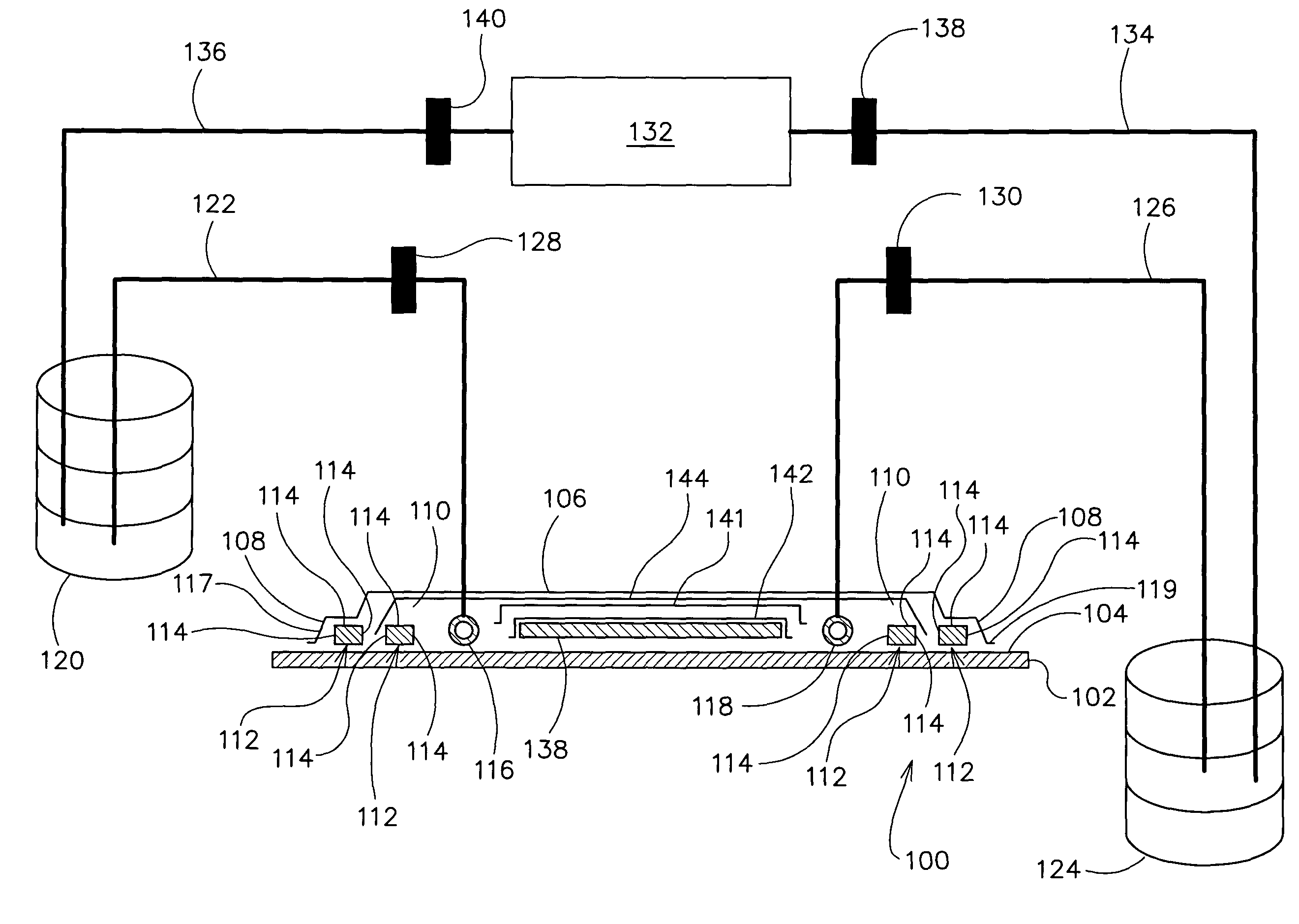
The present invention provides a method and mold for vacuum assisted resin transfer molding a composite structure using fibers and resin. The method includes steps of introducing resin into a closed mold cavity containing fibers and using a vacuum to draw excess resin from the structure prior to curing. The mold includes a tool with a surface shaped to correspond to the composite structure and an inflatable bladder for forcing the structure against the tool surface. The bladder is sealed with the tool surface to form a cavity for containing the structure. The mold also includes a pump for applying a vacuum to the mold to draw excess resin from the structure. The invention also provides a molded composite structure body with a plurality of fiber plies stacked in face to face relation and a resin mixture interspersed between the reinforcing fibers. The technical effects of the invention include improved resin transfer and reduced resin waste during the molding process.

Problems solved by technology

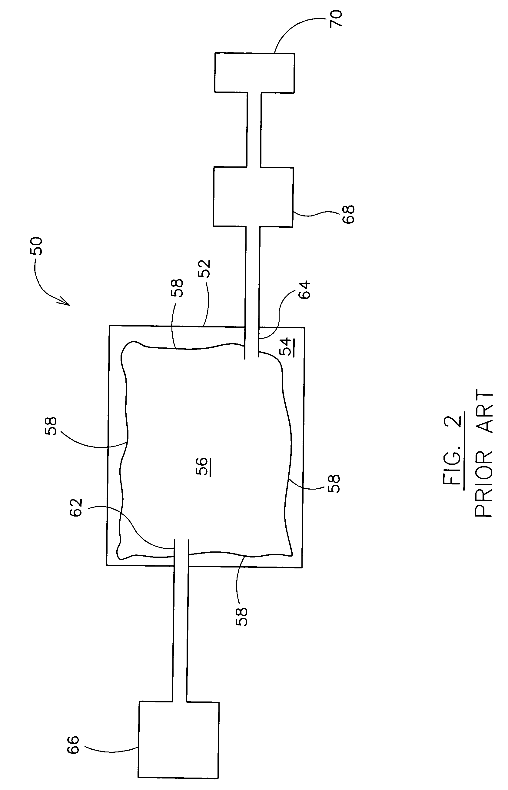
However, due to excess resin infused into the preform, known resin transfer molding processes typically produce finished composite structures that are consistently resin rich, have a high per ply thickness, and have a low fiber volume as compared to traditional autoclave-cured composite structures.

Method used


Image

  • Method for vacuum assisted resin transfer molding
  • Method for vacuum assisted resin transfer molding
  • Method for vacuum assisted resin transfer molding

Examples


Embodiment Construction

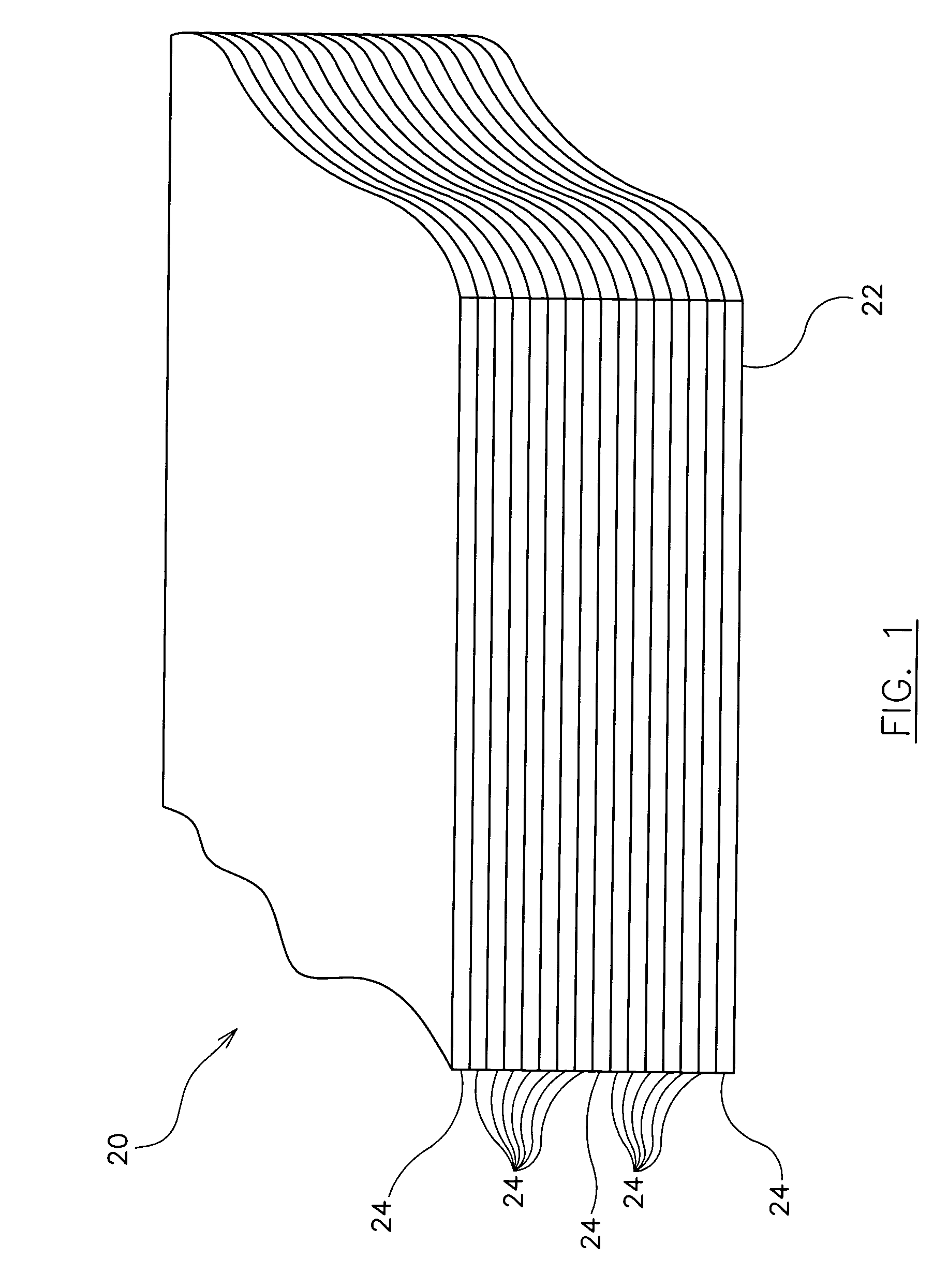
[0014]Referring now the to the drawings, and more specifically to FIG. 1, a composite structure is designated in its entirety by the reference numeral 20. The composite structure 20 is molded using a vacuum assisted resin transfer molding process and includes a body 22 having a plurality of fiber plies 24 stacked in face to face relation in a predetermined order and orientation. Each fiber ply 24 has a resin mixture (not shown) interspersed between a plurality of reinforcing fibers 28. For some applications, the composite structure 20 may include other materials, for example sheets of metal foil, stacked between the fiber plies 24. In one embodiment, the composite structure 20 is an aircraft component, such as, for example, an integrated stiffened structure for an aircraft wing (not shown), a sub-structure for an aircraft wing, a skin panel for an aircraft (not shown), or a control surface for an aircraft. However, it should be understood that the composite structure 20 may be any c...


PUM

PropertyMeasurementUnit
vacuumaaaaaaaaaa
thicknessaaaaaaaaaa
structureaaaaaaaaaa

Abstract

A method for vacuum assisted resin transfer molding a composite structure including fibers at least partially surrounded by resin using a mold including a tool having a surface shaped to correspond to the composite structure and an inflatable bladder for forcing the composite structure against the tool. A resin inlet is connected to a resin source for introducing resin into a mold cavity at least partially defined by the tool surface and the bladder and a vacuum port spaced from the resin inlet. The method includes the steps of opening the mold cavity, loading fibers into the open mold cavity, closing the loaded mold cavity, introducing resin through the resin inlet into the closed mold cavity loaded with fibers, and pulling a vacuum at the resin inlet and the vacuum port to draw excess resin from the structure prior to curing thereof.

Description

[0001]This invention was made with Government support under F33615-98-3-5104 and SCRA Task order 002 under Subrecipient Agreement No. 2001-508, awarded by the United States Air Force. The Government has certain rights in this invention.BACKGROUND OF THE INVENTION[0002]The present invention relates generally to resin transfer molding, and more specifically to a method and apparatus for vacuum assisted resin transfer molding.[0003]As an alternative to molding composite structures using a traditional autoclave, resin transfer molding processes are commonly used to mold fiber / resin composites by infusing a fiber preform with resin under a vacuum. To help achieve even distribution of resin throughout the preform and a predetermined thickness of the finished composite structure, some resin transfer molding processes, such as controlled atmospheric pressure resin infusion, utilize a half-atmosphere vacuum, while others, such as double bag vacuum infusion (DBVI), incorporate multiple vacuum...

Claims


Application Information

Patent Timeline
Patent Type & Authority Patents(United States)
IPC IPC(8): B29C45/14B29C70/44
CPCB29C70/443
Inventor SEWELL, TERRY A.WANTHAL, STEVEN P.
Owner THE BOEING CO
Learn More